NETGEAR, Inc
Trademarks
Technical Support
Statement of Conditions
Certificate of the Manufacturer/Importer
Canada
United States
Europe
Japan
Korea
Lithium Battery Safety Notice
Australia/New Zealand
Rest of World
China RoHS
European Union RoHS
Product and Publication Details
Publication Date June Product Family Wireless Product Name
Model Number
Contents
Chapter Configuring Network Parameters
Chapter Configuring Wlans
Chapter Configuring MAC-Based Authentication
Appendix a Configuring Dhcp with Vendor-Specific Options
Appendix D Related Documents Index
Conventions, Formats, and Scope
About This Manual
How to Print this Manual
How to Use This Manual
Revision History
Xvi About This Manual
Chapter Overview of the WFS709TP
Netgear ProSafe Access Points
WFS709TP System Components
WFS709TP
WFS709TP
Wiring closet Internet
Wireless clients Floor
Data center Automatic RF Channel and Power Settings
RF Monitoring
WFS709TP ProSafe Switches
V1.0, June
WFS709TP Software
Netgear Wireless APs Local WFS709TP Master WFS709TP
Authentication
Basic Wlan Configuration
V1.0, June
Authentication Method Encryption Option
Encryption Options by Authentication Method
Encryption
Vlan
Netgear AP
Floor Wiring closet Internet
Association
Wireless Client Access to the Wlan
Captive Portal
802.1x Authentication
Client Mobility and AP Association
MAC Address Authentication
Configuring and Managing the WFS709TP
V1.0, June
Tools
Configuration Tool
Browser Interface Tools
Menu Description
Wlan
Configuration Pages Basic
V1.0, June
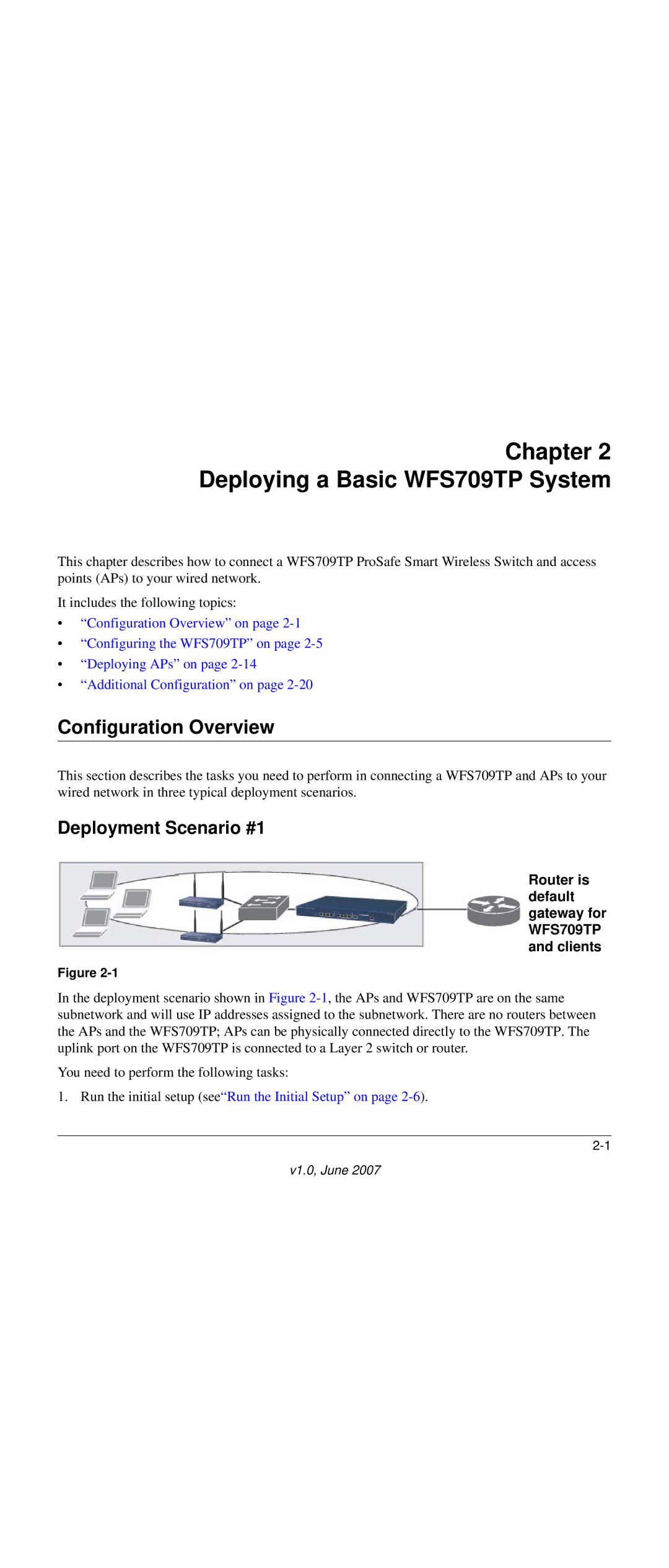
Router is default gateway for WFS709TP and clients
Configuration Overview
Chapter Deploying a Basic WFS709TP System
Deployment Scenario #1
Deployment Scenario #2
Run the initial setup seeRun the Initial Setup on
Deployment Scenario #3
Configuring the WFS709TP
Run the Initial Setup
V1.0, June
Configure the Switch for the Access Points
V1.0, June
Create the Vlan
Configure a Vlan for Network Connection
Configure the Trunk Port
Connect the WFS709TP to the Network
Configure the Default Gateway
Configure the Loopback for the WFS709TP
Deploying APs
Enable APs to Obtain IP Addresses
Enable APs to Connect to the WFS709TP
Locate the WFS709TP
V1.0, June
Provision APs
Install APs
V1.0, June
Additional Configuration
Configuring VLANs
Chapter Configuring Network Parameters
Creating a Vlan
Assigning a Static Address to a Vlan
Cable modem or Bras
Configuring a Vlan to Receive a Dynamic Address
To local
Internet
Enabling the Dhcp Client
Default Gateway from Dhcp
DNS/WINS Server from Dhcp
Configuring Static Routes
Configuring the Loopback IP Address
V1.0, June
V1.0, June
RF Plan Overview
Chapter RF Plan
Task Overview
Before You Begin
Planning Requirements
Using RF Plan
Building List
Building Specification Overview
Building Dimension
V1.0, June
AP Modeling Parameters
Overlap Factor
Radio Type
Design Model
Users
AM Modeling Parameters
Rates
Monitor Rates
Planning Floors
Zoom
Coverage Rate
Coverage
Floor Editor Dialog Box
Area Editor Dialog Box
V1.0, June
Access Point Editor
V1.0, June
Initialize
AP Planning
Viewing the Results
Start
AM Planning
Export Buildings
Exporting and Importing Files
Import Buildings
Locate
Sample Building
RF Plan Example
Create a Building
Building Planning Specifications
Text Box Information
Model the Access Points
Add and Edit a Floor
Model the Air Monitors
Defining Areas
Create a Don’t Care Area
Create a Don’t Deploy Area
Running the AP Plan
Running the AM Plan
Click Save
V1.0, June
Chapter Configuring Wlans
Authentication Methods
Determine the Authentication Method
Method Description
Supported Authentication Servers by Authentication Types
Authentication Server
Authentication Type Authentication Servers
Internal DB
Determine the Default Vlan
Basic Wlan Configuration in the Browser Interface
V1.0, June
Parameter Definition
Wlan Basic Configuration Parameters
Parameter Definition
Example Configuration
V1.0, June
Configuring Global Parameters
Advanced Wlan Configuration in the Browser Interface
Add or Modify SSIDs
Configuring Location-Specific Parameters
Advanced Ssid Configuration Settings
Default Ssid
Configure AP Information
V1.0, June
Configuring Radio Settings
V1.0, June
V1.0, June
Example Configuration
V1.0, June
Power Setting
Channel Setting
Advantages of Using IRM
IntelliFi RF Management
Configuring IRM
V1.0, June
V1.0, June
Configuring an External Radius Server
Chapter Configuring AAA Servers
Radius Server Configuration Information
Parameter Description
Configuring AAA Servers
Internal Database Entry Information
Adding Users to the Internal Database
Logon User Lifetime
Configuring Authentication Timers
V1.0, June
V1.0, June
802.1x Authentication
Chapter Configuring 802.1x Authentication
Authentication
Authentication with a Radius Server
Network authentication Data encryption
Client
Authentication via
Authentication Terminated on WFS709TP
User
Internal database
Configuring 802.1x Authentication
1x Authentication Browser Interface Page Options
802.1x Authentication
Parameter Description Default
Advanced Configuration Options for
Field Description Default
Advanced Authentication Fields
500
Overview of Captive Portal Functions
Chapter Configuring the Captive Portal
Configuring Captive Portal
Configuring Advanced Captive Portal Options
Enabled
Changing the Protocol to Http
Configuring the AAA Server for Captive Portal
Personalizing the Captive Portal
V1.0, June
V1.0, June
Configuring MAC-Based Authentication
Configuring Users
V1.0, June
V1.0, June
Chapter Adding Local WFS709TPs
Moving to a Multi-Switch Environment
Configuring the Local WFS709TP
Configuring Local WFS709TPs
Configuring L2/L3 Settings
Configuring APs
Configuring Trusted Ports
Rebooting APs
Redundancy Configuration
Chapter Configuring Redundancy
Virtual Router Redundancy Protocol
Configuring Local WFS709TP Redundancy
Parameter Explanation Expected or Recommended Values
Vrrp Parameters for Local WFS709TP Redundancy
Master WFS709TP Redundancy
Master-Local WFS709TP Redundancy
Association Function Switch ID
Vrrp Associations
Vlan 1, 2, ... N
Master
Layer
Network
Configuring Redundancy 11-7
11-8 Configuring Redundancy
Rogue/Interfering AP Detection
Configuring Wireless Intrusion Protection
Classifying APs
Enabling AP Learning
Configuring Wireless Intrusion Protection 12-3
AP Classifications
Configuring Rogue AP Detection
FIeld Description
Configuring Misconfigured AP Protection
Misconfigured AP Detection
Valid Channel Types
12-6 Configuring Wireless Intrusion Protection
Configuring Management Users
Chapter Configuring Management Utilities
Snmp for the WFS709TP
Configuring Snmp
Basic WFS709TP Snmp Parameters
Field Description Expected/Recommended Value
SNMPv3 User Details
Snmp for Access Points
Field Description Expected/Recommended Values
Basic Access Point Snmp Parameters
Traps on page 13-9 for a complete list
SNMPv3 Access Point User Details
Configuring Management Utilities 13-7
13-8 Configuring Management Utilities
WFS709TP Traps
Snmp Traps
WFS709TP Snmp Traps
Trap Description Priority Level
Access Point Snmp Traps
Access Point/Air Monitor Traps
Configuring Management Utilities 13-11
WFS709TP Modules
Configuring Logging
Module Description
Configuring Management Utilities 13-13
Creating Guest Accounts
Configuring Management Utilities 13-15
Managing Files on the WFS709TP
Server Type Configuration
Servers for File Transfer
Backing Up and Restoring the Flash File System
Managing Image Files
Copying Other Files
Copying Log Files
Installing a Server Certificate
13-20 Configuring Management Utilities
Voice over IP Proxy ARP
Chapter Configuring WFS709TP for Voice
Battery Boost
Limiting the Number of Active Voice Calls
WPA Fast Handover
Overview
Appendix a Configuring Dhcp with Vendor-Specific Options
Windows-Based Dhcp Servers
Configuring Option
Figure A-1
Figure A-2
Linux Dhcp Servers
V1.0, June
V1.0, June
Window XP Wireless Client Example Configuration
Appendix B Windows Client Example Configuration for
Figure B-1
V1.0, June
Figure B-3
Figure B-4
Figure B-5
Figure B-6
V1.0, June
Creating a New Internal Web
Appendix C Internal Captive Portal
Username
Password
Html Head Body
Basic Html Example
Displaying Authentication Error Message
Installing a New Captive Portal
V1.0, June
Language Customization
Head TitlePortal Login/title
Replace this with a link like the following
Div id=errorbox style=display none
V1.0, June
Figure C-1shows a sample of a translated
Figure C-2
Customizing the Welcome
V1.0, June
Customizing the Pop-Up Box
Customizing the Logged Out Box
V1.0, June
Document Link
Appendix D Related Documents
V1.0, May
Numbers
Index
Netgear FrameMaker Templates for the Reference Print Manual
Index Index-3
Index-4