Model 7112 T1 DSU/CSU
Copyright � 1998 Paradyne Corporation All rights reserved
Contents
Configuring the DSU/CSU
Monitoring the DSU/CSU
Messages and Troubleshooting
MIB Descriptions
Technical Specifications Glossary Index
About This Guide
Document Purpose and Intended Audience
Document Summary
Product-Related Documents
About the T1 DSU/CSU
Model 7112 T1 DSU/CSU Features
Typical Configuration through a T1 network
Typical DSU/CSU Configurations
User Interface Types
Front Panel LED Status Indicators
Network
Rear Panel Interface Connections
Snmp Management Capabilities
Management Information Base MIB Support
Using the Ascii Terminal Interface ATI
Accessing the ATI
Connecting to the Terminal Port
Select
Initiating an ATI Session
Use the screen format
Screen Work Areas
Screen Format Types
What Affects Screen Displays
Press
Status Test Configuration Control
Navigating
Keyboard Keys
Procedure
Example
Switching Between Screen Work Areas
Screen Function Keys
For the screen Select Press Enter to Function
Ending an ATI Session
Using the Ascii Terminal Interface ATI
Configuring the DSU/CSU
Entering Device and System Information
Main Menu → Control → Device
Configuring the DSU/CSU
Configuration Option Areas
Configuration Option Area Configuration Option Set
If you select Then
Accessing and Displaying Configuration Options
Saving Configuration Options
Main Menu → Configuration Load Configuration From
Cross Connect Assignments
Assigning DS0 Channels to the Data Port
Displaying DS0 Channel Assignments
Using the Block or Acami Assignment Method
Clearing DS0 Channel Assignments
Using the Individual Channel Assignment Method
Overview
Security
Creating a Login
Main Menu → Control → Administer Logins
On the Administer Enter Logins screen, for
Resetting the DSU/CSUs COM Port or Factory Defaults
Deleting a Login
If entering yes to prompt Then
ATI Access
Effective Access Levels ATI Access to Menu Functions
Effective Access Level
Controlling Snmp Access
Assigning Snmp Community Names and Access Levels
Connection Failed
Limiting Snmp Access through the IP Addresses
Security
IP Addressing
IP Addressing
IP Addressing Examples
Local Addressing Only No FDL
Subnet
NMS a NMS B
FDL Connection ± Extending Subnet for FDL
LAN a
FDL Connection ± Unique FDL Subnet
Assigning IP Addresses and Subnet Masks
If using Then assign
IP Addressing
What to Monitor
Monitoring the DSU/CSU
Main Menu → Status → Display LEDs
DSU/CSU LEDs
Fail
System LEDs
Network LEDs
SIG ± Network Signal
Alarm
EER ± Excessive Error Rate
Port LEDs
Status Screen Commands
System and Test Status
Main Menu → Status → System and Test Status
Yyyyyyyy
Health and Status Messages
Xxxxxxxx
Self-Test Results
Test Status Messages Meaning
Test Status Messages
Cross Connect Status
Main Menu → Status → Cross Connect Status
Network Time Slot Fields top Indicate
Main Menu → Status → Network Performance Statistics
Network Performance Statistics
Interval Table
Summary Information
Worst Interval
Ethernet Port Status
Hour Totals
Main Menu → Status → Ethernet Port Status
Main Menu → Status → Management Protocol Statistics
Management Protocol Statistics
March
Testing
Detecting Problems
Status Specific Trap Screen
Main Menu → Test
Accessing the Test Menu
Main Menu → Test → Network Tests
Running Network Tests
Payload Loopback
Line Loopback
Repeater Loopback
Test Patterns for the Network
Remote Send Line Loopback
Main Menu → Test → Data Port Tests
Running Data Port Tests
CSU DSU
Data Terminal Loopback
Data Channel Loopback
Send V.54 Up/Down Sequences
Test Patterns for the DTE
Send FT1 Up/Down Sequences
Ending an Active Test
Lamp Test
Messages and Troubleshooting
Configuring Snmp Traps
Snmp Traps
Device Messages 1 What Message Indicates What To Do
Device Messages
Device Messages 2 What Message Indicates What To Do
Troubleshooting 1 Symptom Possible Cause Solutions
Troubleshooting
Troubleshooting 2 Symptom Possible Cause Solutions
Messages and Troubleshooting
Select To Access To Configure
Configuration Option Tables
Self Test
Test Timeout
System Options Menu
Table A-1. System Options
Line Coding Format
Network Interface Options Menu
Table A-2. Network Interface Options 1
Line Framing Format
FDL Management Link
Bit Stuffing Possible Settings 62411, Part68, Disable
Line Build Out LBO Possible Settings 0.0, ±7.5, ±15, ±22.5
Table A-2. Network Interface Options 2
Table A-2. Network Interface Options 3
Network Initiated Line Loopback LLB
Network Initiated Payload Loopback PLB
Table A-2. Network Interface Options 4
Ansi Performance Report Messages
Circuit Identifier
Synchronous Data Port Assignments
Assign By Available Settings Block, ACAMI, Channel
Cross Connect Assignments
Table A-3. Cross Connect Assignments
Invert Transmit Clock
Data Port Options Menu
Table A-4. Data Port Options 1
Port Base Rate
Action on Network Yellow Alarm
Table A-4. Data Port Options 2
Invert Transmit and Received Data
Table A-4. Data Port Options 3
Port Use Possible Settings 802.3, Version 2, Disable
Ethernet Port Options Menu
Table A-5. Ethernet Port Options 1
Character Length
Terminal Port Options
Table A-5. Ethernet Port Options 2
Table A-6. Terminal Port Options 1
Stop Bits
Login Required
Port Access Level Possible Settings Level 1, Level 2, Level
Table A-6. Terminal Port Options 2
Telnet Session Options
Table A-6. Terminal Port Options 3
Table A-7. Telnet Session Options 1
Table A-7. Telnet Session Options 2
Snmp Menu
General Snmp Management Options
Table A-8. General Snmp Management Options 1
Table A-9. Snmp NMS Security Options 1
Name 2 Access
Snmp NMS Security Options
Table A-8. General Snmp Management Options 2
Table A-9. Snmp NMS Security Options 2
Access Level
Number of Trap Managers
Snmp Traps Options
Table A-10. Snmp Traps Options 1
Snmp Traps
Link Trap Interfaces
Link Traps Possible Settings Disable, Up, Down, Both
Table A-10. Snmp Traps Options 2
Enterprise Specific Traps
Worksheets
Configuration Worksheets
Configuration Option Settings default in Bold
Enable, Disable
Disable, Enable
ESF, D4
Blank
Internal, External
Nx64, Nx56
Ethernet Port
Configuration Option Settings
Snmp NMS Security
Snmp
Worksheets
MIB II ± RFC 1213 and RFC
MIB Descriptions
System Group
SysDescr system
SysName system
Internet 4 ± Layer
Interfaces Group
Physical 1 ± Layer
Datalink/subnetwork
EthernetCsmacd6 ± Used for
Version Hardware Revision º
Up1
Testing3 state
IfInErrors ifEntry
IfInOctets ifEntry
Extension to Interface Table ifXTable
IfName ifXEntry
IfXEntry
Interface Stack Group
IfStackEntry1
IfStackEntry2
Interface Test Table
Generic Receive Address Table
IP Group
On next
Invalid
Exist. The following objects must
Be specified
Do not specify the following
Icmp Group
TCP Group
UDP Group
Transmission
Snmp Group
Transmission Group
Table C-6. Transmission Group Objects Description
Dsx1ESF2 ± Indicates
DS1 Near End Group Configuration Table Objects
Dsx1ConfigEntry
DS1/E1 ± RFC
Dsx1SendNoCode1 ±
Dsx1SendResetCode4 ±
Dsx1B8ZS2 ± Indicates
Dsx1AMI5 ± Indicates
Dsx1PayloadLoop2 ±
Dsx1NoAlarm1 ± No
Dsx1LossOfSignal64 ±
Dsx1NoLoop1 ± The T1
Dsx1other1 ± Snmp
LoopTiming1 ±
LocalTiming2 ±
ThroughTiming3 ±
Dsx1CurrentEntry
DS1 Near End Group Current Table Objects
DS1 Near End Group Interval Table Objects
Dsx1IntervalEntry
Dsx1IntervalEntry10
Dsx1TotalEntry
DS1 Near End Group Total Table Objects
Number of RS-232-Like Ports Object
Ethernet-Like MIB ± RFC
RS-232-Like MIB ± RFC
DS1 Fractional Group
Rs232PortEntry
Disabled2 ± Does not
Asynchronous Port Table Objects
Rs232AsyncPortEntry
Rs232SyncPortEntry
Synchronous Port Table Objects
Rs232InSigEntry
Input Signal Table Objects
Rs232OutSigEntry
Output Signal Table Objects
TestMon Qrss wellKnownTests
Generic Interface Extension MIB ± RFC
Generic Interface Test Table Objects
IfExtnsTestEntry
± Starts a Monitor 511 test on the interface
NotSupported4 ± Requested
InSyncNoBitErrors
InSyncWithBitErrors
InProgress3 ± Test is
Device Traps, pdn-traps pdn-common
Device Configuration Variable pdn-common
Enterprise MIB Object
Device Security, pdn-security pdn-common
MIB Descriptions
Snmp Trap Description Possible Cause
Standards Compliance for Snmp Traps
Trap warmStart
Trap authentificationFailure
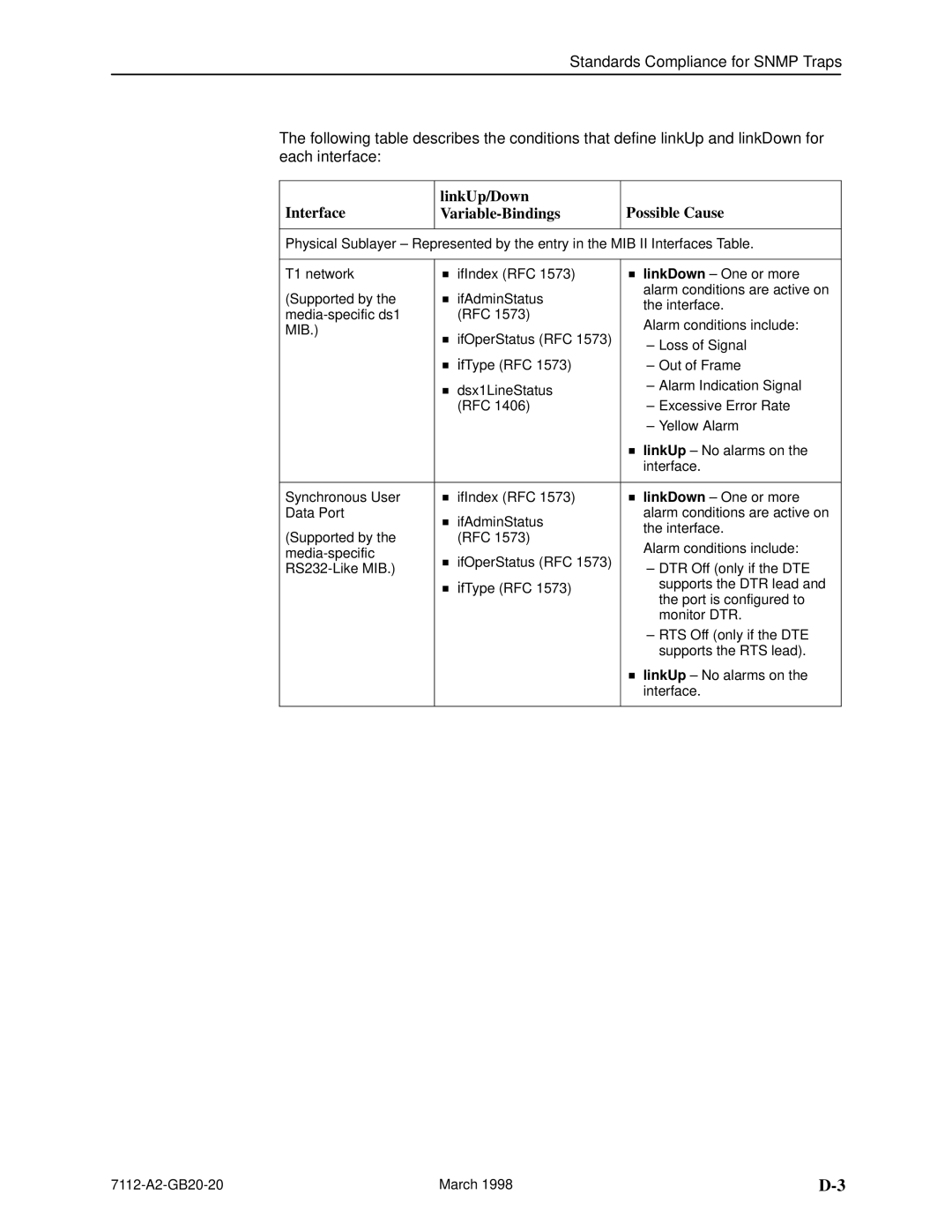
Traps linkUp and linkDown
Interface LinkUp/Down Variable-Bindings Possible Cause
Trap What It Indicates Possible Cause
Traps enterpriseSpecific
Page
Standards Compliance for Snmp Traps
Cabling Overview
Cables and Pin Assignments
Modular RJ48C-to-CA81A T1 Network Interface Cable
Modular RJ48C-to-RJ48C T1 Network Interface Cable
Use Pin #
Terminal Port EIA-232 Connector
10BaseT Connector
Signal Direction Pin #
Pin
Serial Crossover Cable
DTE V.35 Connector
Signal
Direction Pin Socket Connector
Cables and Pin Assignments
Model 7112 DSU/CSU Technical Specifications 1
Technical Specifications
Model 7112 DSU/CSU Technical Specifications 2
Glossary
Channel allocation
Configuration option
Default
Digital signal
Enterprise-specific
Factory defaults
EIA-232
Enterprise MIB
Multiplexing
Reset
Loopback
Manager Snmp
Subnet address
RS-232
Self-test
Subnet
Yellow Alarm
In-8 pattern
Pattern
Numbers
Index
IN-2
IN-3
IN-4