5.2.4Homing Move

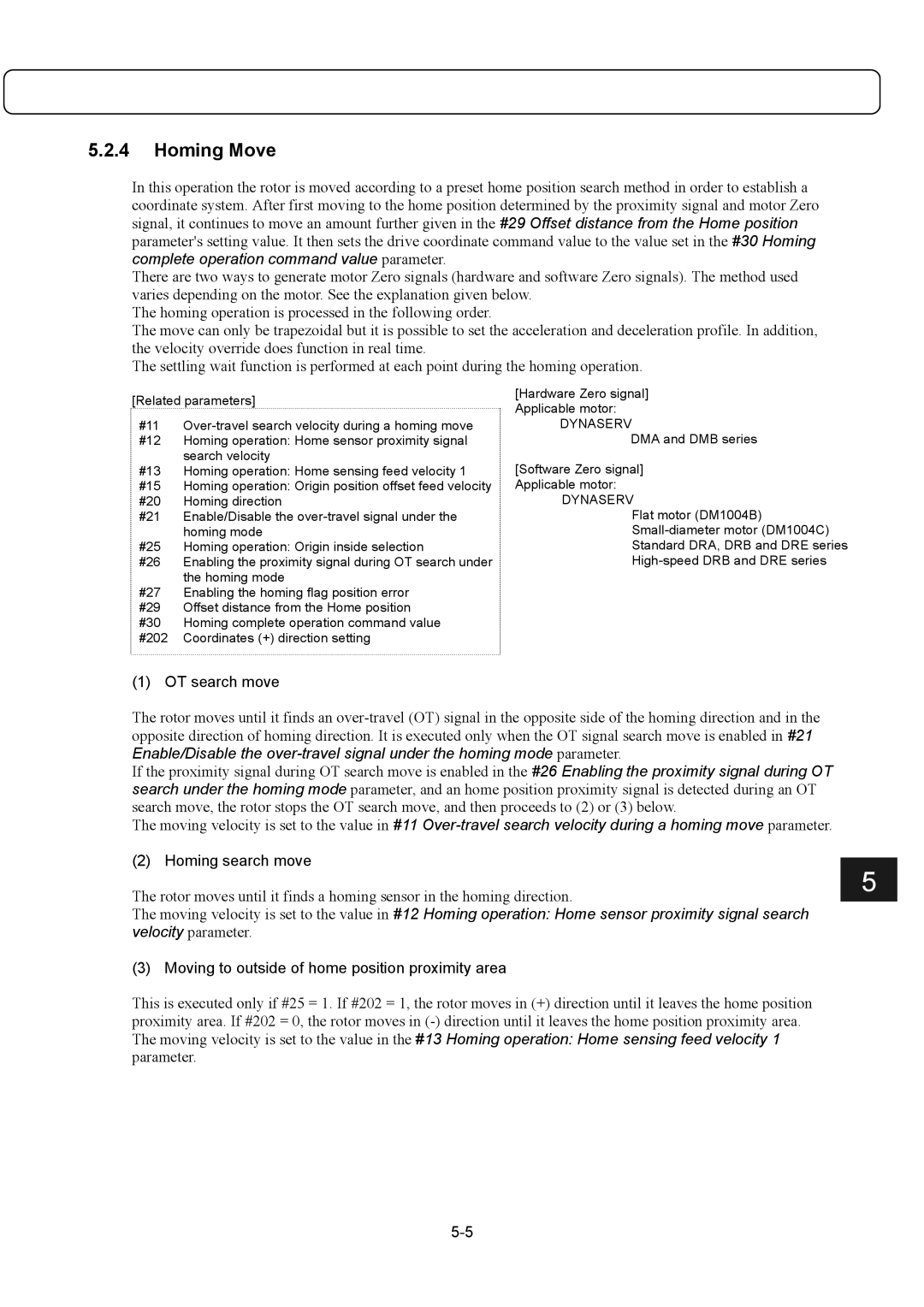
In this operation the rotor is moved according to a preset home position search method in order to establish a coordinate system. After first moving to the home position determined by the proximity signal and motor Zero signal, it continues to move an amount further given in the #29 Offset distance from the Home position parameter's setting value. It then sets the drive coordinate command value to the value set in the #30 Homing complete operation command value parameter.

There are two ways to generate motor Zero signals (hardware and software Zero signals). The method used varies depending on the motor. See the explanation given below.

The homing operation is processed in the following order.

The move can only be trapezoidal but it is possible to set the acceleration and deceleration profile. In addition, the velocity override does function in real time.

The settling wait function is performed at each point during the homing operation.

[Related parameters]

[Hardware Zero signal]

Applicable motor:


#11

Over-travel search velocity during a homing move

DYNASERV

#12

Homing operation: Home sensor proximity signal

DMA and DMB series


search velocity

[Software Zero signal]

#13

Homing operation: Home sensing feed velocity 1

#15

Homing operation: Origin position offset feed velocity

Applicable motor:

#20

Homing direction

DYNASERV

#21

Enable/Disable the over-travel signal under the

Flat motor (DM1004B)


homing mode

Small-diameter motor (DM1004C)

#25

Homing operation: Origin inside selection

Standard DRA, DRB and DRE series

#26

Enabling the proximity signal during OT search under

High-speed DRB and DRE series


the homing mode


#27

Enabling the homing flag position error


#29

Offset distance from the Home position


#30

Homing complete operation command value


#202

Coordinates (+) direction setting


(1) OT search move

The rotor moves until it finds an over-travel (OT) signal in the opposite side of the homing direction and in the opposite direction of homing direction. It is executed only when the OT signal search move is enabled in #21 Enable/Disable the over-travel signal under the homing mode parameter.

If the proximity signal during OT search move is enabled in the #26 Enabling the proximity signal during OT search under the homing mode parameter, and an home position proximity signal is detected during an OT search move, the rotor stops the OT search move, and then proceeds to (2) or (3) below.

The moving velocity is set to the value in #11 Over-travel search velocity during a homing move parameter.

(2) Homing search move

The rotor moves until it finds a homing sensor in the homing direction.

5

The moving velocity is set to the value in #12 Homing operation: Home sensor proximity signal search velocity parameter.

(3) Moving to outside of home position proximity area

This is executed only if #25 = 1. If #202 = 1, the rotor moves in (+) direction until it leaves the home position proximity area. If #202 = 0, the rotor moves in (-) direction until it leaves the home position proximity area. The moving velocity is set to the value in the #13 Homing operation: Home sensing feed velocity 1 parameter.

5-5

Page 59
Image 59
Parker Hannifin G2 Homing Move, OT search move, Homing search move, Moving to outside of home position proximity area

G2 specifications

Parker Hannifin G2 is a state-of-the-art platform designed to transform the way industries approach fluid and motion control. As a leader in motion and control technologies, Parker Hannifin has integrated cutting-edge features into the G2, making it a standout choice for various applications, including aerospace, industrial automation, and hydraulic systems.

One of the main features of the Parker Hannifin G2 series is its modular design. This allows users to customize the configuration according to their specific needs, facilitating enhanced versatility and efficiency. The modular approach supports different valve and actuator options, enabling seamless integration with existing systems and allowing for future expansions.

The G2 is equipped with advanced connectivity options, including Ethernet and fieldbus solutions. These technologies enable real-time data exchange and remote monitoring, ensuring optimized performance and reduced downtime. Users can leverage this connectivity to implement preventive maintenance strategies, thereby increasing the overall reliability of their operations.

Another notable characteristic of the G2 platform is its intelligent control algorithms. These algorithms allow for enhanced process automation, ensuring that systems can adapt dynamically to changing operating conditions. The result is improved energy efficiency and lower operational costs, critical factors in today’s competitive market.

Durability is a key aspect of the G2 series as well. Constructed with high-quality materials, the platform is designed to withstand harsh industrial environments, making it ideal for applications where reliability is paramount. Additionally, its compact footprint enables easy installation and integration into existing setups without requiring extensive modifications.

The user interface of the G2 is exceptionally user-friendly. With intuitive design and advanced graphical displays, operators can easily access performance data, diagnostics, and system parameters. This ease of use not only improves operational efficiency but also enhances training processes for new personnel.

In summary, Parker Hannifin G2 represents a significant advancement in fluid and motion control technology. Its modular design, advanced connectivity, intelligent control algorithms, durability, and user-friendly interface make it a compelling choice for industries seeking to enhance their operations. With these features, the G2 empowers businesses to achieve their efficiency, reliability, and performance goals.