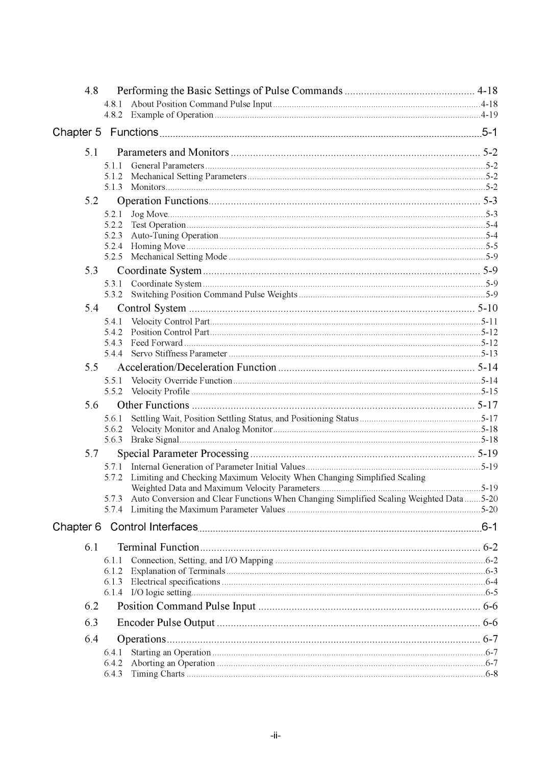
G2 specifications
Parker Hannifin G2 is a state-of-the-art platform designed to transform the way industries approach fluid and motion control. As a leader in motion and control technologies, Parker Hannifin has integrated cutting-edge features into the G2, making it a standout choice for various applications, including aerospace, industrial automation, and hydraulic systems.One of the main features of the Parker Hannifin G2 series is its modular design. This allows users to customize the configuration according to their specific needs, facilitating enhanced versatility and efficiency. The modular approach supports different valve and actuator options, enabling seamless integration with existing systems and allowing for future expansions.
The G2 is equipped with advanced connectivity options, including Ethernet and fieldbus solutions. These technologies enable real-time data exchange and remote monitoring, ensuring optimized performance and reduced downtime. Users can leverage this connectivity to implement preventive maintenance strategies, thereby increasing the overall reliability of their operations.
Another notable characteristic of the G2 platform is its intelligent control algorithms. These algorithms allow for enhanced process automation, ensuring that systems can adapt dynamically to changing operating conditions. The result is improved energy efficiency and lower operational costs, critical factors in today’s competitive market.
Durability is a key aspect of the G2 series as well. Constructed with high-quality materials, the platform is designed to withstand harsh industrial environments, making it ideal for applications where reliability is paramount. Additionally, its compact footprint enables easy installation and integration into existing setups without requiring extensive modifications.
The user interface of the G2 is exceptionally user-friendly. With intuitive design and advanced graphical displays, operators can easily access performance data, diagnostics, and system parameters. This ease of use not only improves operational efficiency but also enhances training processes for new personnel.
In summary, Parker Hannifin G2 represents a significant advancement in fluid and motion control technology. Its modular design, advanced connectivity, intelligent control algorithms, durability, and user-friendly interface make it a compelling choice for industries seeking to enhance their operations. With these features, the G2 empowers businesses to achieve their efficiency, reliability, and performance goals.

