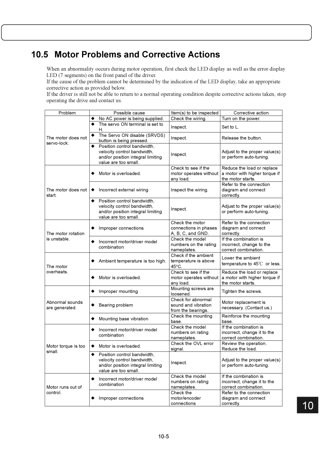
10.5 Motor Problems and Corrective Actions

When an abnormality occurs during motor operation, first check the LED display as well as the error display LED (7 segments) on the front panel of the driver.

If the cause of the problem cannot be determined by the indication of the LED display, take an appropriate corrective action as provided below.

If the driver is still not be able to return to a normal operating condition despite corrective actions taken, stop operating the drive and contact us.

Problem


Possible cause

Item(s) to be inspected

Corrective action


!

No AC power is being supplied.

Check the wiring.

Turn on the power.


! The servo ON terminal is set to

Inspect.

Set to L.


H.


The motor does not

!

The Servo ON disable (SRVDS)

Inspect.

Release the button.


servo-lock.


button is being pressed.


!

Position control bandwidth,


Adjust to the proper value(s)


velocity control bandwidth,

Inspect.


and/or position integral limiting

or perform auto-tuning.


value are too small.


Check to see if the

Reduce the load or replace


!

Motor is overloaded.

motor operates without

a motor with higher torque if


any load.

the motor starts.


Refer to the connection


The motor does not

!

Incorrect external wiring

Inspect the wiring.

diagram and connect


start.


correctly.


!

Position control bandwidth,


Adjust to the proper value(s)


velocity control bandwidth,

Inspect.


and/or position integral limiting

or perform auto-tuning.


value are too small.


Check the motor

Refer to the connection


!

Improper connections

connections in phases

diagram and connect


The motor rotation


A, B, C, and GND.

correctly.


is unstable.

!

Incorrect motor/driver model

Check the model

If the combination is


numbers on the rating

incorrect, change to the


combination


nameplates.

correct combination.


Check if the ambient

Lower the ambient


! Ambient temperature is too high.

temperature is above


The motor

temperature to 45or less.


45°C.


overheats.


Check to see if the

Reduce the load or replace


!

Motor is overloaded.

motor operates without

a motor with higher torque if


any load.

the motor starts.


!

Improper mounting

Mounting screws are

Tighten the screws.


loosened.


Abnormal sounds


Check for abnormal

Motor replacement is


!

Bearing problem

sound and vibration


are generated.

necessary. (Contact us.)


from the bearings.


!

Mounting base vibration

Check the mounting

Reinforce the mounting


base.

base.


!

Incorrect motor/driver model

Check the model

If the combination is


numbers on rating

incorrect, change it to the


combination


nameplates.

correct combination.


Motor torque is too

! Motor is overloaded.

Check the OVL error

Review the operation.


signal.

Reduce the load.


small.


!

Position control bandwidth,


Adjust to the proper value(s)


velocity control bandwidth,

Inspect.


and/or position integral limiting

or perform auto-tuning.


value are too small.


!

Incorrect motor/driver model

Check the model

If the combination is


numbers on rating

incorrect, change it to the


combination


Motor runs out of


nameplates.

correct combination.


control.


Check the

Refer to the connection


!

Improper connections

motor/encoder

diagram and connect


10


connections

correctly.


10-5

Page 135
Image 135
Parker Hannifin G2 manual Motor Problems and Corrective Actions, 10-5

G2 specifications

Parker Hannifin G2 is a state-of-the-art platform designed to transform the way industries approach fluid and motion control. As a leader in motion and control technologies, Parker Hannifin has integrated cutting-edge features into the G2, making it a standout choice for various applications, including aerospace, industrial automation, and hydraulic systems.

One of the main features of the Parker Hannifin G2 series is its modular design. This allows users to customize the configuration according to their specific needs, facilitating enhanced versatility and efficiency. The modular approach supports different valve and actuator options, enabling seamless integration with existing systems and allowing for future expansions.

The G2 is equipped with advanced connectivity options, including Ethernet and fieldbus solutions. These technologies enable real-time data exchange and remote monitoring, ensuring optimized performance and reduced downtime. Users can leverage this connectivity to implement preventive maintenance strategies, thereby increasing the overall reliability of their operations.

Another notable characteristic of the G2 platform is its intelligent control algorithms. These algorithms allow for enhanced process automation, ensuring that systems can adapt dynamically to changing operating conditions. The result is improved energy efficiency and lower operational costs, critical factors in today’s competitive market.

Durability is a key aspect of the G2 series as well. Constructed with high-quality materials, the platform is designed to withstand harsh industrial environments, making it ideal for applications where reliability is paramount. Additionally, its compact footprint enables easy installation and integration into existing setups without requiring extensive modifications.

The user interface of the G2 is exceptionally user-friendly. With intuitive design and advanced graphical displays, operators can easily access performance data, diagnostics, and system parameters. This ease of use not only improves operational efficiency but also enhances training processes for new personnel.

In summary, Parker Hannifin G2 represents a significant advancement in fluid and motion control technology. Its modular design, advanced connectivity, intelligent control algorithms, durability, and user-friendly interface make it a compelling choice for industries seeking to enhance their operations. With these features, the G2 empowers businesses to achieve their efficiency, reliability, and performance goals.