SANbox 6140 Intelligent Storage Router
Document Revision History
SANbox 6140 Intelligent Storage Router User’s Guide
SANbox 6140 Intelligent Storage Router User’s Guide
Page
Table of Contents
Planning
Removal/Replacement
FI0154601-00 C
Command Reference
Configuring Chap
Simple Network Management Protocol Snmp
FI0154601-00 C
List of Tables
FI0154601-00 C
Intended Audience
Related Materials
Safety Communications Statements
Federal Communications Commission FCC Class a Statement
CE Statement
Laser Safety Information
Vcci Class a Statement
Electrostatic Discharge Sensitivity Esds Precautions
Accessible Parts
General Public License
Preamble
FI0154601-00 C
FI0154601-00 C
FI0154601-00 C
No Warranty
END of Terms and Conditions
How to Apply These Terms to Your New Programs
Ty Coon, President of Vice
Technical Support
Availability
Training
Contact Information
General Description
System Fault LED Blink Patterns
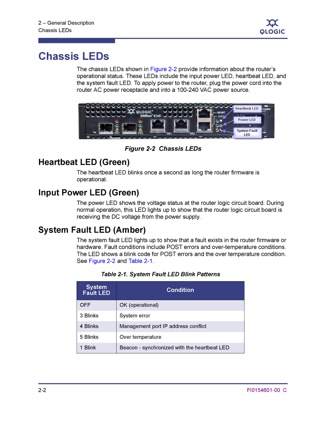
Input Power LED Green
System Fault LED Amber
Chassis LEDs
Maintenance Button
Reset a Router
Chassis Controls
Enable Dhcp
Reset and Select Boot Image
Reset IP Address
Restore Factory Defaults
Fibre Channel Ports
Power OFF
Power on Before firmware Initialization
Fibre Channel Port LEDs
Fibre Channel Transceivers
Gigabit Ethernet Port LEDs
Ethernet Port-Management
Serial Port
Serial Port Pin Identification
Planning
Devices
Fibre Channel
Device Access
FC Performance
ISCSI
Bandwidth
Related performance characteristics include the following
ISCSI Performance
Latency
Performance Tuning
T1 / DS-1 1.554 Mbits/Sec
T3 / DS-3 45 Mbits/Sec
Mbits/Sec
OC-1 50 Mbits/Sec
OC-3 150 Mbits/Sec
Multiple Routers
Management
OC-12 and Above 621 Mbits/Sec
Recovery
Services
Security
FI0154601-00 C
Site Requirements
Management Workstation
Management Workstation Requirements
Power Requirements
Environmental Conditions
Installing the SANbox 6140 Router
SANbox 6140 Router and Accessories
Pre-installation Checklist
Pre-installation Check List
Install the Transceivers
Mount the Router
Configure the Management Workstation
Connect the Management Workstation to the Router
Setting the Workstation IP Address
Configuring the Workstation Serial Port
Connect the router to the power see
Install SANsurfer iSCSI/FC Router Manager
Windows Installation
Select the Intelligent Storage Routers icon
Linux Installation
For Linux, enter the following command
Start SANsurfer iSCSI/FC Router Manager
Connect the Router to AC Power
Configure the Router
Telnet 10.0.0.1 username guest password
Cable Devices to the Router
Using the CLI to Install Firmware
Firmware Installation
Using SANsurfer iSCSI/FC Router Manager to Install Firmware
Enter your username and password. For example
At the ftp prompt, type bin to set binary mode. For example
Enter reboot. The following message displays
Type y to reboot the system
Following message displays
Chassis Diagnostics
This section describes the following conditions
Power-On Self-Test Diagnostics
Input Power LED is Off
System Fault LED is On
Heartbeat Blink Pattern
System Error Blink Pattern
LED Blink Patterns
OK Operational
Over-Temperature Blink Pattern
Management Port IP Address Conflict Blink Pattern
Recovering a Router
FI0154601-00 C
Removal/Replacement
SFP Transceiver Removal and Replacement
Router Removal and Replacement
Replacement
Removal
SANsurfer iSCSI/FC Router Manager
Introduction
Menu Bar
SANsurfer Router Manager Main Window Sections
Settings Menu
File Menu
View Menu
Wizards Menu
7shows the Wizards drop-down menu
Help Menu
8shows the Help drop-down menu
Tool Bar
Action Menu
SANsurfer iSCSI/FC Router Manager Action Menu
System Tree Window
11shows the system tree
Status Icons and Text
12 Component Information
Router
FC and iSCSI Ports
Discovered iSCSI Initiators
FC discovered target icons
FC Discovered Targets
ISCSI Presented Targets
LUN icons
SANbox 6140 Router
Information
Basic Information
Connectivity
Management Information
14 Information Tabbed Page Management Information
FI0154601-00 C
NTP Server Information
15 Information Tabbed Page NTP Server Information
Security Information
16 Information Tabbed Page Security Information
Snmp Configuration
Snmp Management
Snmp Management tabbed page provides the following options
Snmp Settings
Snmp Trap Receivers
FC Ports
„ Link Status Port status, either Link Up or Link Down
Advanced Configuration
19 FC Port Advanced Configuration Tabbed
Save FC Port Settings Complete
Click OK to close the message box
Statistics
20 FC Port Statistics
ISCSI Ports
ISCSI port display consists of three tabs „ Information
ISCSI Port Network Settings
ISCSI Port Information
„ Actual
FI0154601-00 C
Enable iSNS
22 Enable iSNS Server with IPv4 Address
24 Advanced Configuration Tabbed
Advanced iSCSI Port Parameters
FI0154601-00 C
Discovered iSCSI Initiators
25 Discovered iSCSI Initiator Tabbed Pages
Initiator Information
Chap Settings
LUN List
26 LUN List Tabbed
FC Discovered Targets
27 FC Discovered Targets Information Tabbed
28 LUN List Tabbed
ISCSI Presented Target List Tabbed
29 iSCSI Presented Target List Tabbed
Discovered LUN Information Tabbed
30shows the Discovered LUN Information tabbed
FI0154601-00 C
LUN Presentation Information 1 and 2 Tabbed Pages
31shows the LUN Presentation Information 1 tabbed
ISCSI Presented Targets
32 iSCSI Presented Targets Tabbed Pages
Information Tabbed
LUN Presentation Information Tabbed
33 LUN Presentation Information Tabbed
Discovered LUN Information
34 Discovered LUN Information Tabbed
Wizards
35 Wizards Menu
Configuration Wizard
36 iSCSI Port Selection Dialog Box
„ IP Address „ Subnet Mask „ Gateway
Click Next
38 iSCSI Port IPv6 Settings Panel
ISCSI Port IPv6 Settings Panel appears, as shown in Figure
39 Confirm Changes Dialog Box
Confirm Changes dialog box displays, as shown in Figure
Enter the password, then click OK
Wizard displays a Warning message, as shown in Figure
42 iSCSI Port Configuration Status
System displays the Finish dialog box, as shown in Figure
Read the information, then click Finish
Add Initiator Wizard
44 Create an Initiator Dialog Box
45 Security Check Dialog Box
Security Check dialog box displays, as shown in Figure
FW Update Wizard
47 Router Selection Dialog Box
48 Firmware File Selection Dialog Box
49 Confirm Changes Dialog Box
51 Firmware Update Status Dialog Box-Progress
Presentation Wizard
53 Device Selection Dialog Box
54 LUN Mapping Dialog Box
LUN Mapping dialog box displays, as shown in Figure
55 Confirm Changes Dialog Box
57 LUN Masking Configuration Status Dialog Box
Finish dialog box displays, as shown in Figure
59 Finish Dialog Box
Click Finish to complete the Presentation wizard
Presentation Unmap Wizard
60 Device Selection Dialog Box
61 Select the Initiator for the LUN Presentation Dialog Box
Confirm the LUN mapping changes by clicking Next
63 Security Check Dialog Box
Click Finish to close the wizard
Command Reference
Logging on to a SAN Router
Saving and Restoring Router Configurations
Working with SAN Router Configurations
Modifying a Configuration
„ LUN Mapping, which uses the following command
Save Router Configuration and Persistence
Restore Router Configuration and Persistence
Command
Commands
CLI command syntax is as follows
Table A-1. Command Line Completion
Syntax
Admin Command
Authority
Keywords
Beacon Command
Beacon
Off
Logs
Clear Command
Clear logs or stats
Stats
MMDDhhmmCCYY
Date Command
Syntax date
Keywords MMDDhhmmCCYY
Restore save
FRU Command
Keywords restore
Syntax fru
Examples The following example shows the help command
Help Command
Displays a list of the commands and their syntax
Authority None Syntax help
Luns Lunmask Memory Mgmt Ntp Presentedtargets snmp
History
Displays a numbered list of the previously entered commands
Examples The following example shows the history command
Authority None Syntax history
Image
Image Command
Cleanup
Unpack file
Add
Initiator Command
Initiator
Mod
Please select an Initiator from the list above q to quit
Logout Command
Examples The following example shows the logout command
Authority None Syntax logout
Lunmask Command
Lunmask
Seagate
Examples The following example shows the passwd command
Password Command
Changes the guest and administrator passwords
Syntax passwd
Ping Command
Examples The following example shows the ping command
Syntax ping
Quit Command
Examples The following example shows the quit command
Authority None Syntax quit
Restarts the router firmware Authority Admin session
Reboot Command
Syntax reboot
Examples The following example shows the reboot command
Reset Factory Command
Save Command
Traces
Set Command
Syntax set
Keywords chap
Following example shows the set chap command
Set Chap Command
Configures general router parameters
Set chap
Set FC Command
Set fc portnum
Portnum
FI0154601-00 C
Number of the iSCSI port to be configured
Set iSCSI Command
Configures an iSCSI port
Following example shows the set iscsi command
FI0154601-00 C
Number of the iSCSI port to be configured for iSNS
Set iSNS Command
Configures iSNS parameters for an iSCSI port
Following example shows the set isns command
Following example shows the set mgmt command
Set Mgmt Command
Configures the router’s management port 10/100
Set mgmt
Following example shows the set ntp command
Set NTP Command
Configures the NTP parameters
Set ntp
Set snmp
Set Snmp Command
Specifies the setting of the trap destinations
Trapdestinations
That have been changed Will now be saved
Following example shows the set system command
Set System Command
Configures the general router parameters
Set system
Following example shows the set vlan command
Set Vlan Command
Configures the router’s Vlan parameters
Set vlan
Initiators fc or iscsi
Show Command
Authority None Syntax show chap
Initiatorslunmask
Presentedtargets fc or iscsi
Luninfo
Luns
Targets fc or iscsi
Examples The following example shows the show fc command
Show Chap Command
Displays Chap configuration for iSCSI nodes
Authority None Syntax
Show fc portnum
Show FC Command
None
Identifies the number of the FC port to display
Syntax show initiators fc
Show Initiators Command
Keywords fc
Specifies the display of Fibre Channel initiators
Show Initiators LUN Mask Command
Authority None
Syntax show initiatorslunmask
Show iSCSI Command
Show iscsi portnum
Number of the iSCSI port to be displayed
IPv6 Link Local
Show iSNS Command
Following example shows the show isns command
Show isns portnum
Displays the router event log
Show Logs Command
Examples The following example shows the show logs command
Show logs
Show Luninfo Command
Show luninfo
Displays LUN information for each target
Show LUNs Command
Examples The following example shows the show luns command
Show luns
Show Lunmask Command
Syntax show lunmask
Show Mgmt Command
Following example shows the show mgmt command
Show mgmt
Show NTP Command
Show ntp
Show Presented Targets Command
Syntax show presentedtargets fc
Specifies the display of FC presented targets
10.3.5.66
Show Snmp Command
Show snmp
Show Stats Command
Displays the router statistics FC and iSCSI
Show stats
60362392962831
55036896842234
IP Fragment Rcvd Out of Order
Show System Command
Show system
Scsi
Show Targets Command
Show targets
Specifies the display of FC targets
Following example shows the show targets iscsi command
Show Vlan Command
Syntax show vlan portnum
Keywords portnum
Target
Target Command
Following example shows the target add command
Not supported
TargetMap Command
Following example shows the targetmap add command
Targetmap
Following example shows the targetmap rm remove command
Traceroute Command
Syntax traceroute
Configuring Chap
CLI-Discovery Session-Bi-directional Chap
CLI-Discovery Session-Uni-directional Chap
Click Advanced Select Chap Login Information
Select Mutual Authentication
Click Discovery
Click OK Click OK. The initiator completes the normal login
CLI-Normal Session-Bi-directional Chap
Use Set Chap
Click Advanced Configuration Select Enable Chap
CLI-Normal Session-Uni-directional Chap
GUI-Discovery Session-Bi-directional Chap
Click Add Enter the address of the iSCSI port of the bridge
GUI-Discovery Session-Uni-directional Chap
Type the IQN name string
Click OK Click OK. The initiator completes discovery
GUI-Normal Session-Bi-directional Chap
Click Advanced Click Chap Login Information
Click Information Select Enable Chap
Click Advanced
Click OK Click OK. The initiator completes normal login
GUI-Normal Session-Uni-directional Chap
FI0154601-00 C
Application Modules
Table C-1. Application Modules-Informational Log Messages
ISCSI Driver
Table C-2. Scsi Driver-Informational Log Messages
Fibre Channel Driver
Table C-3. Fibre Channel Driver-Informational Log Messages
Error Log Messages
Table C-4. Application Module-Error Log Messages
Capacity
Table C-4. Application Module-Error Log Messages
FI0154601-00 C
FI0154601-00 C
Table C-5. iSCSI. Driver-Error Log Messages
Table C-6. Fibre Channel Driver-Error Log Messages
Log Messages
Log Messages Error Log Messages
Table C-7. User Modules-Error Log Messages
User Modules
Log Message
Table C-8. System-Error Log Messages
System
Fatal Log Messages
Table C-9. iSCSI Driver-Fatal Log Messages
Table C-9. iSCSI Driver-Fatal Log Messages
FC Driver
Table C-10. Fibre Channel Driver-Fatal Log Messages
Table C-10. Fibre Channel Driver-Fatal Log Messages
Table C-11. System-Fatal Log Messages
FI0154601-00 C
Snmp Properties
Table D-1. Snmp Properties
Snmp Trap Configuration
Table D-2. Snmp Trap Configuration Parameters
QsrHwVersion
System Information
QsrSerialNumber
QsrSwVersion
Network Port Table
QsrNwPortEntry
QsrNwPortAddressMode
QsrNwPortRole
QsrNwPortIndex
QsrIPAddressType
Fibre Channel Port Table
QsrFcPortIndex
QsrFcPortEntry
QsrFcPortRole
QsrFcPortNodeWwn
Sensor Table
QsrSensorType
QsrSensorEntry
Sensor entry consists of the following sequence of objects
QsrSensorIndex
QsrLowerThreshold
QsrSensorValue
QsrUpperThreshold
QsrSensorState
QsrEventDescription
Notification Objects
QsrEventSeverity
QsrEventTimeStamp
Network Port Down Notification
Agent Start Up Notification
Agent Shut Down Notification
Fibre Channel Port Down Notification
Sensor Notification
Generic Notification
FI0154601-00 C
AC power CE statement Account, guest A-2
Index
Index-2 FI0154601-00 C
FI0154601-00 C Index-3
LUN
FI0154601-00 C Index-5
Index-6 FI0154601-00 C
TCP
Index-8 FI0154601-00 C