4. Software Implementation of the Gateway
4.2.6. Configuring Inputs from the Gateway
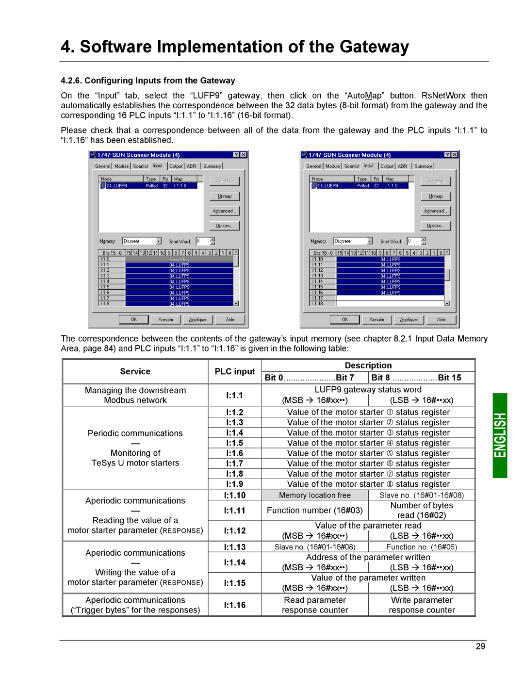
On the “Input” tab, select the “LUFP9” gateway, then click on the “AutoMap” button. RsNetWorx then automatically establishes the correspondence between the 32 data bytes
Please check that a correspondence between all of the data from the gateway and the PLC inputs “I:1.1” to “I:1.16” has been established.
The correspondence between the contents of the gateway’s input memory (see chapter 8.2.1 Input Data Memory Area, page 84) and PLC inputs “I:1.1” to “I:1.16” is given in the following table:
Service | PLC input | Description | ||
Bit 0......................Bit 7 | Bit 8 ...................Bit 15 | |||
Managing the downstream | I:1.1 | LUFP9 gateway status word | ||
Modbus network | (MSB Æ 16#xx••) | (LSB Æ 16#••xx) | ||
| ||||
| I:1.2 | Value of the motor starter c status register | ||
Periodic communications | I:1.3 | Value of the motor starter d status register | ||
I:1.4 | Value of the motor starter e status register | |||
— | I:1.5 | Value of the motor starter f status register | ||
Monitoring of | I:1.6 | Value of the motor starter g status register | ||
TeSys U motor starters | I:1.7 | Value of the motor starter h status register | ||
| I:1.8 | Value of the motor starter i status register | ||
| I:1.9 | Value of the motor starter j status register | ||
Aperiodic communications | I:1.10 | Memory location free | Slave no. | |
I:1.11 | Function number (16#03) | Number of bytes | ||
— | ||||
read (16#02) | ||||
Reading the value of a |
|
| ||
| Value of the parameter read | |||
motor starter parameter (RESPONSE) | I:1.12 | |||
(MSB Æ 16#xx••) | (LSB Æ 16#••xx) | |||
|
| |||
Aperiodic communications | I:1.13 | Slave no. | Function no. (16#06) | |
I:1.14 | Address of the parameter written | |||
— | ||||
(MSB Æ 16#xx••) | (LSB Æ 16#••xx) | |||
Writing the value of a |
| |||
| Value of the parameter written | |||
motor starter parameter (RESPONSE) | I:1.15 | |||
(MSB Æ 16#xx••) | (LSB Æ 16#••xx) | |||
|
| |||
Aperiodic communications | I:1.16 | Read parameter | Write parameter | |
(“Trigger bytes” for the responses) | response counter | response counter | ||
| ||||
29