4. Software Implementation of the Gateway
4.2.5. Configuring the DeviceNet Scanner
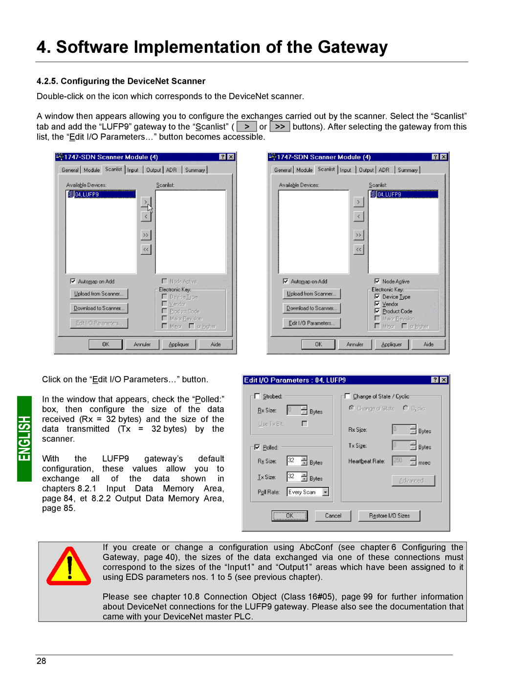
A window then appears allowing you to configure the exchanges carried out by the scanner. Select the “Scanlist” tab and add the “LUFP9” gateway to the “Scanlist” ( > or >> buttons). After selecting the gateway from this list, the “Edit I/O Parameters…” button becomes accessible.
Click on the “Edit I/O Parameters…” button.
In the window that appears, check the “Polled:” box, then configure the size of the data received (Rx = 32 bytes) and the size of the data transmitted (Tx = 32 bytes) by the scanner.
With the LUFP9 gateway’s default configuration, these values allow you to exchange all of the data shown in chapters 8.2.1 Input Data Memory Area, page 84, et 8.2.2 Output Data Memory Area, page 85.
If you create or change a configuration using AbcConf (see chapter 6 Configuring the Gateway, page 40), the sizes of the data exchanged via one of these connections must correspond to the sizes of the “Input1” and “Output1” areas which have been assigned to it using EDS parameters nos. 1 to 5 (see previous chapter).
Please see chapter 10.8 Connection Object (Class 16#05), page 99 for further information about DeviceNet connections for the LUFP9 gateway. Please also see the documentation that came with your DeviceNet master PLC.
28