6. Configuring the Gateway
3)Changing the location of the Modbus data transmitted into the gateway’s memory: As the number of bytes written (see previous step) has increased from 2 to 4, the Modbus data to be transmitted to the “TeSys U n°4” motor starter must be placed at a different location in the gateway’s memory, and the size of the memory occupied must also be adjusted appropriately.
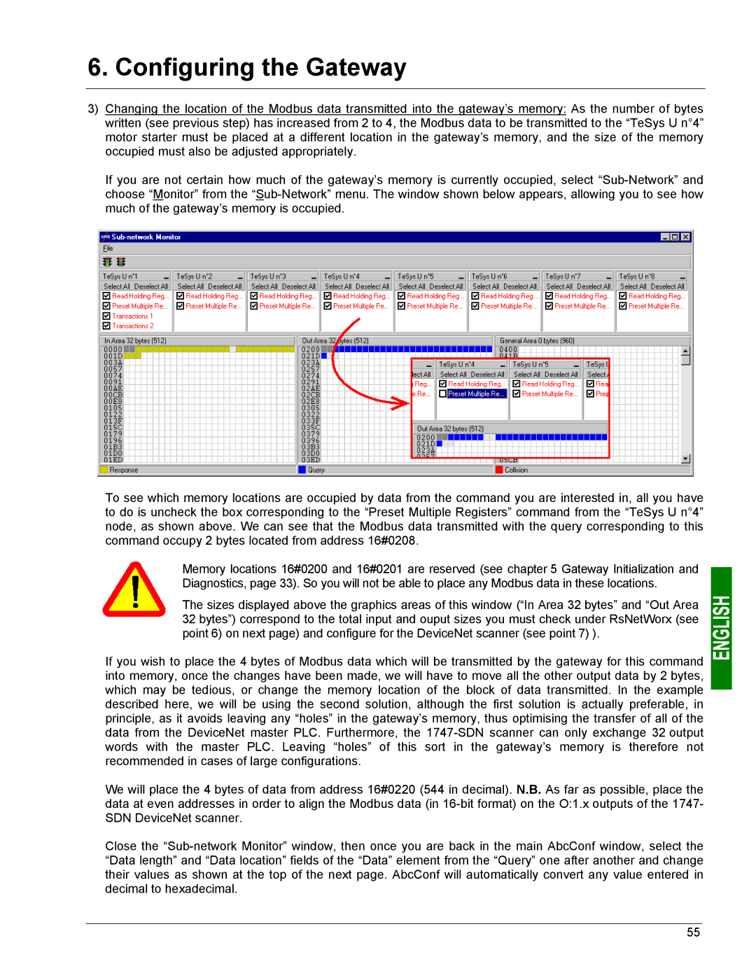
If you are not certain how much of the gateway’s memory is currently occupied, select
To see which memory locations are occupied by data from the command you are interested in, all you have to do is uncheck the box corresponding to the “Preset Multiple Registers” command from the “TeSys U n°4” node, as shown above. We can see that the Modbus data transmitted with the query corresponding to this command occupy 2 bytes located from address 16#0208.
Memory locations 16#0200 and 16#0201 are reserved (see chapter 5 Gateway Initialization and Diagnostics, page 33). So you will not be able to place any Modbus data in these locations.
The sizes displayed above the graphics areas of this window (“In Area 32 bytes” and “Out Area 32 bytes”) correspond to the total input and ouput sizes you must check under RsNetWorx (see point 6) on next page) and configure for the DeviceNet scanner (see point 7) ).
If you wish to place the 4 bytes of Modbus data which will be transmitted by the gateway for this command into memory, once the changes have been made, we will have to move all the other output data by 2 bytes, which may be tedious, or change the memory location of the block of data transmitted. In the example described here, we will be using the second solution, although the first solution is actually preferable, in principle, as it avoids leaving any “holes” in the gateway’s memory, thus optimising the transfer of all of the data from the DeviceNet master PLC. Furthermore, the
We will place the 4 bytes of data from address 16#0220 (544 in decimal). N.B. As far as possible, place the data at even addresses in order to align the Modbus data (in
Close the
55