6. Configuring the Gateway
Configuration | Description |
|
element |
| |
|
| |
Update mode | This element is used to specify the transmission mode for the query on the Modbus | |
| network. It takes one of the following four values: | |
| - Cyclically | Default communication mode. The query is transmitted |
| periodically on the Modbus network (see “Update time”). | |
| - On data change | The gateway transmits the query on the Modbus network |
| when at least one item of data from this query is changed by the DeviceNet master. | |
| So this is an aperiodic communication mode. | |
| - Single Shot | This transmission mode only allows a single Modbus |
| exchange for the whole of the time that the gateway is operating. This exchange | |
| takes place just after the initialization of the gateway. | |
| - Change of state on trigger | With this aperiodic communication mode, the Modbus |
| query is sent every time that the DeviceNet master changes the value of an | |
| counter designated by the “Trigger byte address” element. For instance, this is the | |
| case with the queries | associated with “Transactions 1” and “Transactions 2” |
| personalized commands for the “TeSys U n°1” node of the gateway’s default | |
| configuration. These queries are transmitted when the values of the related “trigger | |
| bytes” (addresses 16#021E and 16#021F) are changed by the DeviceNet master. | |
| Please see the description of this element for further information about how to use | |
| this communication mode. | |
Update time | This element is only used by the gateway if “Update mode” is set to “Cyclically”. In this case, it | |
(10ms) | specifies the query’s transmission period on the Modbus network. | |
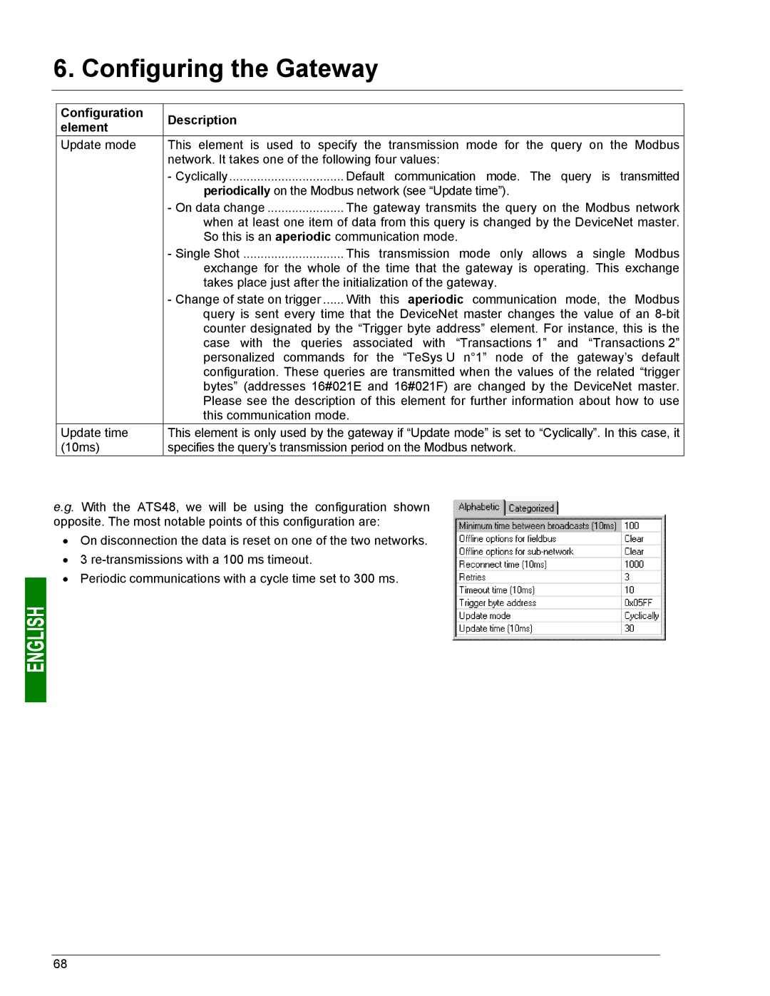
e.g. With the ATS48, we will be using the configuration shown opposite. The most notable points of this configuration are:
•On disconnection the data is reset on one of the two networks.
•3
•Periodic communications with a cycle time set to 300 ms.
68