5. Gateway Initialization and Diagnostics
5.1.2. Gateway Status Word
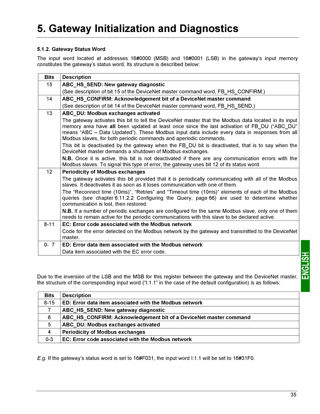
The input word located at addresses 16#0000 (MSB) and 16#0001 (LSB) in the gateway’s input memory constitutes the gateway’s status word. Its structure is described below:
Bits | Description |
15ABC_HS_SEND: New gateway diagnostic
(See description of bit 15 of the DeviceNet master command word, FB_HS_CONFIRM.)
14ABC_HS_CONFIRM: Acknowledgement bit of a DeviceNet master command (See description of bit 14 of the DeviceNet master command word, FB_HS_SEND.)
13ABC_DU: Modbus exchanges activated
The gateway activates this bit to tell the DeviceNet master that the Modbus data located in its input memory area have all been updated at least once since the last activation of FB_DU (“ABC_DU” means “ABC – Data Updated”). These Modbus input data include every data in responses from all Modbus slaves, for both periodic commands and aperiodic commands.
This bit is deactivated by the gateway when the FB_DU bit is deactivated, that is to say when the DeviceNet master demands a shutdown of Modbus exchanges.
N.B. Once it is active, this bit is not deactivated if there are any communication errors with the Modbus slaves. To signal this type of error, the gateway uses bit 12 of its status word.
12Periodicity of Modbus exchanges
The gateway activates this bit provided that it is periodically communicating with all of the Modbus slaves. It deactivates it as soon as it loses communication with one of them.
The “Reconnect time (10ms)”, “Retries” and “Timeout time (10ms)” elements of each of the Modbus queries (see chapter 6.11.2.2 Configuring the Query, page 66) are used to determine whether communication is lost, then restored.
N.B. If a number of periodic exchanges are configured for the same Modbus slave, only one of them needs to remain active for the periodic communications with this slave to be declared active.
8-11 EC: Error code associated with the Modbus network
Code for the error detected on the Modbus network by the gateway and transmitted to the DeviceNet master.
0- 7 ED: Error data item associated with the Modbus network
Data item associated with the EC error code.
Due to the inversion of the LSB and the MSB for this register between the gateway and the DeviceNet master, the structure of the corresponding input word (“I:1.1” in the case of the default configuration) is as follows:
Bits | Description |
ED: Error data item associated with the Modbus network | |
7 | ABC_HS_SEND: New gateway diagnostic |
6 | ABC_HS_CONFIRM: Acknowledgement bit of a DeviceNet master command |
5 | ABC_DU: Modbus exchanges activated |
4 | Periodicity of Modbus exchanges |
EC: Error code associated with the Modbus network |
E.g. If the gateway’s status word is set to 16#F031, the input word I:1.1 will be set to 16#31F0.
35
