6. Configuring the Gateway
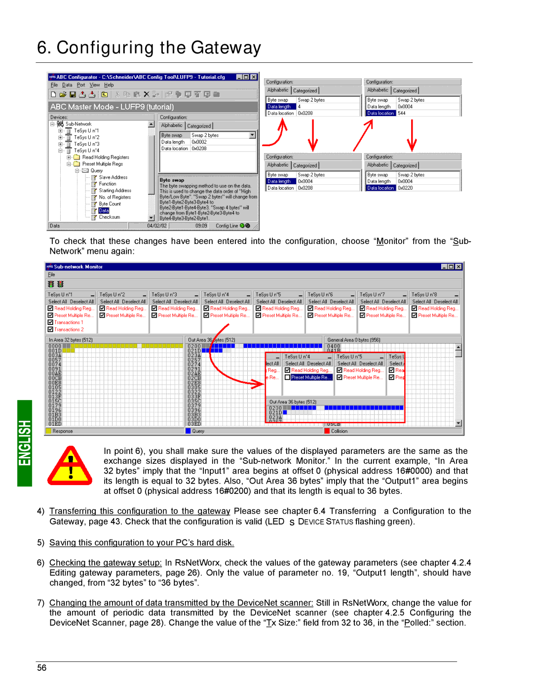
To check that these changes have been entered into the configuration, choose “Monitor” from the “Sub- Network” menu again:
In point 6), you shall make sure the values of the displayed parameters are the same as the exchange sizes displayed in the
4) Transferring this configuration to the gateway Please see chapter 6.4 Transferring a Configuration to the Gateway, page 43. Check that the configuration is valid (LED s DEVICE STATUS flashing green).
5)Saving this configuration to your PC’s hard disk.
6)Checking the gateway setup: In RsNetWorx, check the values of the gateway parameters (see chapter 4.2.4 Editing gateway parameters, page 26). Only the value of parameter no. 19, “Output1 length”, should have changed, from “32 bytes” to “36 bytes”.
7)Changing the amount of data transmitted by the DeviceNet scanner: Still in RsNetWorx, change the value for the amount of periodic data transmitted by the DeviceNet scanner (see chapter 4.2.5 Configuring the DeviceNet Scanner, page 28). Change the value of the “Tx Size:” field from 32 to 36, in the “Polled:” section.
56