6. Configuring the Gateway
6.11. Adding and Setting Up a Modbus Command
6.11.1. With TeSys U Motor Starters
With TeSys U motor starters, the main use of adding a Modbus command consists of allowing you to control or monitor additional registers, without having to change the elements in the default configuration. So, the operation of the periodic and aperiodic communication services remains the same as for the default configuration, unlike the operations described in the various parts of chapter 6.8 Changing the Periodic Data Exchanged With a Modbus Slave, page 48.
Instead of adding a command and fully configuring it, it is a better idea to copy one of the two default commands for TeSys U motor starters, “Read Holding Registers” (reading/monitoring) or “Preset Multiple Registers” (writing/controlling), and to paste it into the list of Modbus commands for the appropriate node.
To copy an already configured Modbus command, select it, then choose “Copy” from the menu whose name corresponds to the name of the selected command. Keyboard shortcut: “Ctrl C”. Then continue using one of the two methods shown below:
a)Select the node corresponding to the Modbus slave for which you wish to add this command (e.g. “TeSys U n°4”), then choose “Paste” from the menu whose name corresponds to the selected node. A new command is added after all the other configured commands for this node. The whole of its configuration is identical to that for the previously copied command. Keyboard shortcut: “Ctrl V”.
b)Select one of the commands for the node involved, then choose “Insert” from the menu whose name corresponds to the selected command. A new command is added just before the one which is selected. The whole of its configuration is identical to that for the previously copied command.
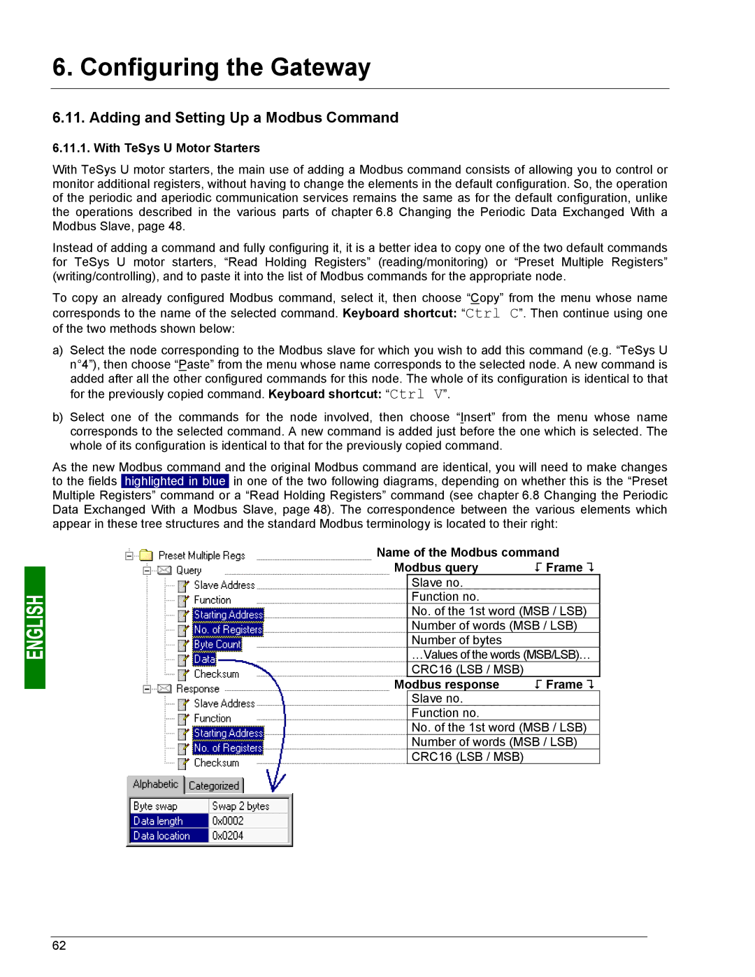
As the new Modbus command and the original Modbus command are identical, you will need to make changes to the fields highlighted in blue in one of the two following diagrams, depending on whether this is the “Preset Multiple Registers” command or a “Read Holding Registers” command (see chapter 6.8 Changing the Periodic Data Exchanged With a Modbus Slave, page 48). The correspondence between the various elements which appear in these tree structures and the standard Modbus terminology is located to their right:
Name of the Modbus command
Modbus query | ! Frame " |
Slave no.
Function no.
No. of the 1st word (MSB / LSB)
Number of words (MSB / LSB)
Number of bytes
…Values of the words (MSB/LSB)…
CRC16 (LSB / MSB)
Modbus response | ! Frame " |
Slave no.
Function no.
No. of the 1st word (MSB / LSB)
Number of words (MSB / LSB)
CRC16 (LSB / MSB)
62