6. Configuring the Gateway
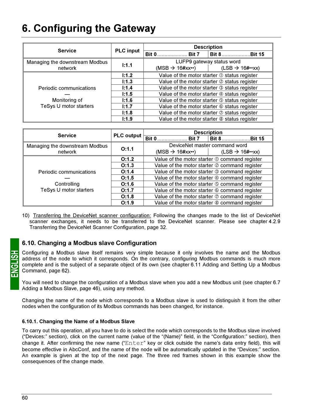
Service | PLC input | Description | ||
Bit 0 ..................... Bit 7 | Bit 8....................Bit 15 | |||
Managing the downstream Modbus | I:1.1 | LUFP9 gateway status word | ||
network | (MSB Æ 16#xx••) | (LSB Æ 16#••xx) | ||
| ||||
| I:1.2 | Value of the motor starter c status register | ||
Periodic communications | I:1.3 | Value of the motor starter d status register | ||
I:1.4 | Value of the motor starter e status register | |||
— | I:1.5 | Value of the motor starter f status register | ||
Monitoring of | I:1.6 | Value of the motor starter g status register | ||
TeSys U motor starters | I:1.7 | Value of the motor starter h status register | ||
| I:1.8 | Value of the motor starter i status register | ||
| I:1.9 | Value of the motor starter j status register | ||
|
|
| ||
Service | PLC output | Description | ||
Bit 0 ..................... Bit 7 | Bit 8....................Bit 15 | |||
Managing the downstream Modbus | O:1.1 | DeviceNet master command word | ||
network | (MSB Æ 16#xx••) | (LSB Æ 16#••xx) | ||
| ||||
| O:1.2 | Value of the motor starter c command register | ||
Periodic communications | O:1.3 | Value of the motor starter d command register | ||
O:1.4 | Value of the motor starter e command register | |||
— | O:1.5 | Value of the motor starter f command register | ||
Controlling | O:1.6 | Value of the motor starter g command register | ||
TeSys U motor starters | O:1.7 | Value of the motor starter h command register | ||
| O:1.8 | Value of the motor starter i command register | ||
| O:1.9 | Value of the motor starter j command register | ||
10)Transferring the DeviceNet scanner configuration: Following the changes made to the list of DeviceNet scanner exchanges, it needs to be transferred to the DeviceNet scanner. Please see chapter 4.2.9 Transferring the DeviceNet Scanner Configuration, page 32.
6.10. Changing a Modbus slave Configuration
Configuring a Modbus slave itself remains very simple because it only involves the name and the Modbus address of the node to which it corresponds. On the contrary, configuring Modbus commands is much more complete and is the subject of a separate object of its own (see chapter 6.11 Adding and Setting Up a Modbus Command, page 62).
You will need to change the configuration of a Modbus slave when you add a new Modbus unit (see chapter 6.7 Adding a Modbus Slave, page 46), using any method.
Changing the name of the node which corresponds to a Modbus slave is used to distinguish it from the other nodes when the configuration of its Modbus commands has been changed, for instance.
6.10.1. Changing the Name of a Modbus Slave
To carry out this operation, all you have to do is select the node which corresponds to the Modbus slave involved (“Devices:” section), click on the current name (value of the “(Name)” field, in the “Configuration:” section), then change it. After confirming the new name (“Enter” key or click outside the name’s data entry field), this will become effective in AbcConf, and the name of the node will be automatically updated in the “Devices:” section. An example is given at the top of the next page. The three red frames shown in this example show the consequences of the change made.
60