9. Appendix C: Practical Example (RSLogix 500)
Address | Symbol | Description | |
S:24 | INDEX_SYS | Index register used in indexed addressing (prefix: ‘#’) | |
T4:1 | TIMEOUT_WR_PARAM | Timer for the timeout of the parameter writing command | |
(3 seconds) | |||
|
|
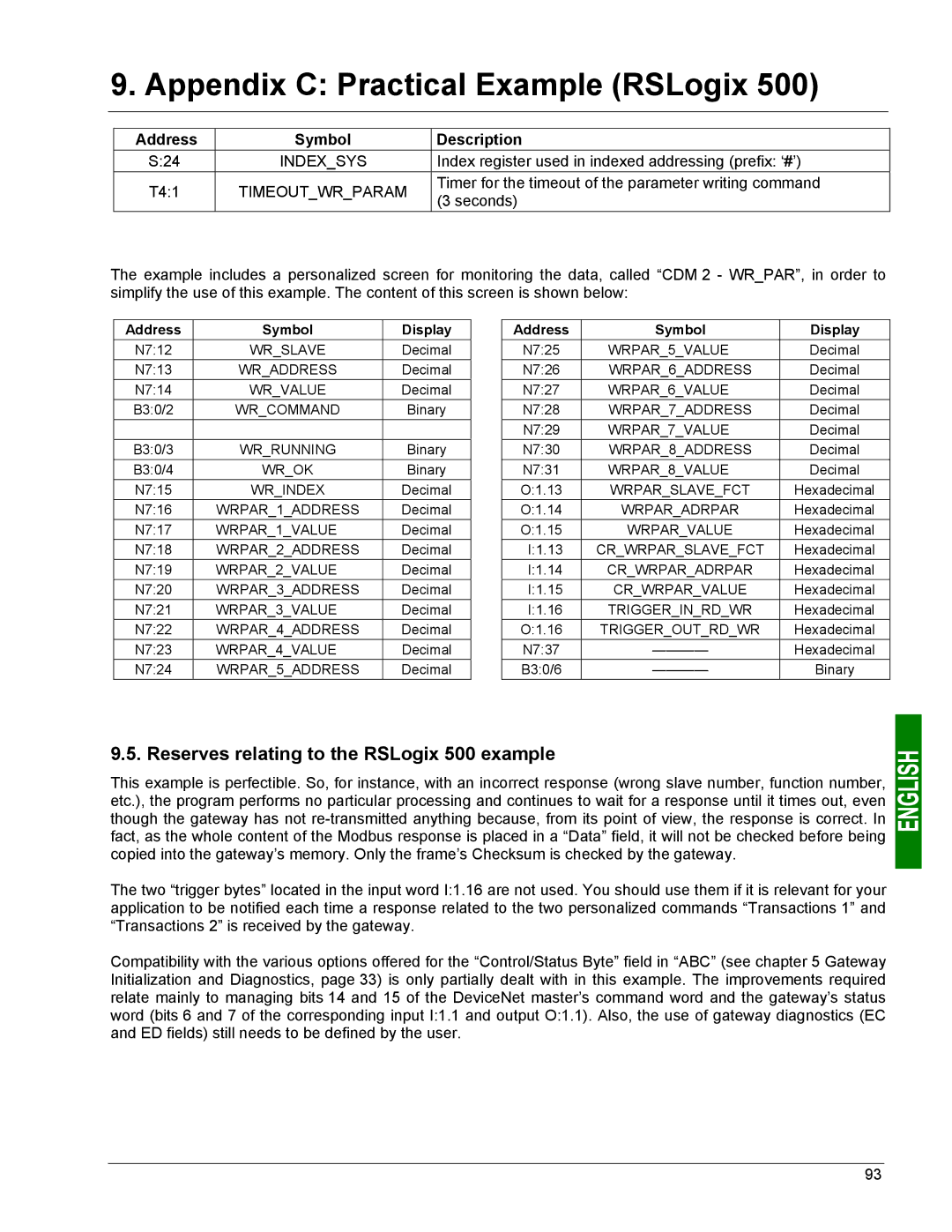
The example includes a personalized screen for monitoring the data, called “CDM 2 - WR_PAR”, in order to simplify the use of this example. The content of this screen is shown below:
Address | Symbol | Display |
N7:12 | WR_SLAVE | Decimal |
N7:13 | WR_ADDRESS | Decimal |
N7:14 | WR_VALUE | Decimal |
B3:0/2 | WR_COMMAND | Binary |
|
|
|
B3:0/3 | WR_RUNNING | Binary |
B3:0/4 | WR_OK | Binary |
N7:15 | WR_INDEX | Decimal |
N7:16 | WRPAR_1_ADDRESS | Decimal |
N7:17 | WRPAR_1_VALUE | Decimal |
N7:18 | WRPAR_2_ADDRESS | Decimal |
N7:19 | WRPAR_2_VALUE | Decimal |
N7:20 | WRPAR_3_ADDRESS | Decimal |
N7:21 | WRPAR_3_VALUE | Decimal |
N7:22 | WRPAR_4_ADDRESS | Decimal |
N7:23 | WRPAR_4_VALUE | Decimal |
N7:24 | WRPAR_5_ADDRESS | Decimal |
Address | Symbol | Display |
N7:25 | WRPAR_5_VALUE | Decimal |
N7:26 | WRPAR_6_ADDRESS | Decimal |
N7:27 | WRPAR_6_VALUE | Decimal |
N7:28 | WRPAR_7_ADDRESS | Decimal |
N7:29 | WRPAR_7_VALUE | Decimal |
N7:30 | WRPAR_8_ADDRESS | Decimal |
N7:31 | WRPAR_8_VALUE | Decimal |
O:1.13 | WRPAR_SLAVE_FCT | Hexadecimal |
O:1.14 | WRPAR_ADRPAR | Hexadecimal |
O:1.15 | WRPAR_VALUE | Hexadecimal |
I:1.13 | CR_WRPAR_SLAVE_FCT | Hexadecimal |
I:1.14 | CR_WRPAR_ADRPAR | Hexadecimal |
I:1.15 | CR_WRPAR_VALUE | Hexadecimal |
I:1.16 | TRIGGER_IN_RD_WR | Hexadecimal |
O:1.16 | TRIGGER_OUT_RD_WR | Hexadecimal |
N7:37 | Hexadecimal | |
B3:0/6 | Binary |
9.5. Reserves relating to the RSLogix 500 example
This example is perfectible. So, for instance, with an incorrect response (wrong slave number, function number, etc.), the program performs no particular processing and continues to wait for a response until it times out, even though the gateway has not
The two “trigger bytes” located in the input word I:1.16 are not used. You should use them if it is relevant for your application to be notified each time a response related to the two personalized commands “Transactions 1” and “Transactions 2” is received by the gateway.
Compatibility with the various options offered for the “Control/Status Byte” field in “ABC” (see chapter 5 Gateway Initialization and Diagnostics, page 33) is only partially dealt with in this example. The improvements required relate mainly to managing bits 14 and 15 of the DeviceNet master’s command word and the gateway’s status word (bits 6 and 7 of the corresponding input I:1.1 and output O:1.1). Also, the use of gateway diagnostics (EC and ED fields) still needs to be defined by the user.
93