9. Appendix C: Practical Example (RSLogix 500)
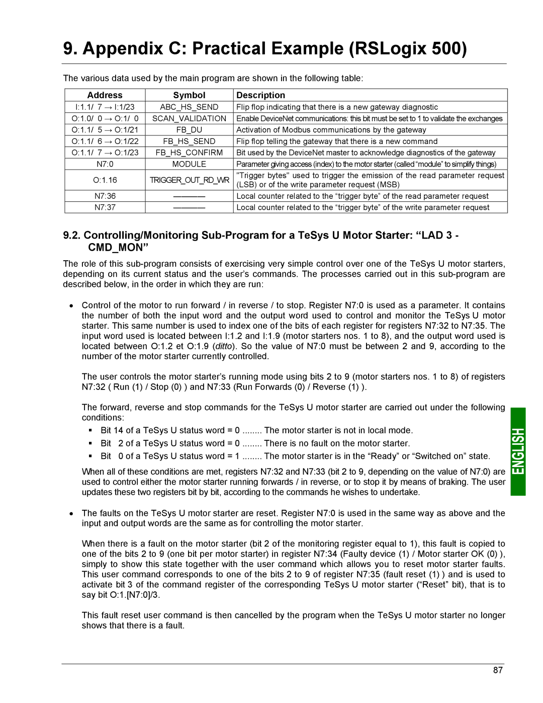
The various data used by the main program are shown in the following table:
Address | Symbol | Description | ||
I:1.1/ | 7 | → I:1/23 | ABC_HS_SEND | Flip flop indicating that there is a new gateway diagnostic |
O:1.0/ | 0 | → O:1/ 0 | SCAN_VALIDATION | Enable DeviceNet communications: this bit must be set to 1 to validate the exchanges |
O:1.1/ | 5 | → O:1/21 | FB_DU | Activation of Modbus communications by the gateway |
O:1.1/ | 6 | → O:1/22 | FB_HS_SEND | Flip flop telling the gateway that there is a new command |
O:1.1/ | 7 | → O:1/23 | FB_HS_CONFIRM | Bit used by the DeviceNet master to acknowledge diagnostics of the gateway |
| N7:0 | MODULE | Parameter giving access (index) to the motor starter (called “module” to simplify things) | |
O:1.16 | TRIGGER_OUT_RD_WR | "Trigger bytes" used to trigger the emission of the read parameter request | ||
|
|
|
| (LSB) or of the write parameter request (MSB) |
| N7:36 | Local counter related to the “trigger byte” of the read parameter request | ||
| N7:37 | Local counter related to the “trigger byte” of the write parameter request | ||
9.2.Controlling/Monitoring
The role of this
•Control of the motor to run forward / in reverse / to stop. Register N7:0 is used as a parameter. It contains the number of both the input word and the output word used to control and monitor the TeSys U motor starter. This same number is used to index one of the bits of each register for registers N7:32 to N7:35. The input word used is located between I:1.2 and I:1.9 (motor starters nos. 1 to 8), and the output word used is located between O:1.2 et O:1.9 (ditto). So the value of N7:0 must be between 2 and 9, according to the number of the motor starter currently controlled.
The user controls the motor starter’s running mode using bits 2 to 9 (motor starters nos. 1 to 8) of registers N7:32 ( Run (1) / Stop (0) ) and N7:33 (Run Forwards (0) / Reverse (1) ).
The forward, reverse and stop commands for the TeSys U motor starter are carried out under the following conditions:
Bit 14 of a TeSys U status word = 0 ........ The motor starter is not in local mode.
| Bit | 2 of a TeSys U status word = 0 | There is no fault on the motor starter. |
| Bit | 0 of a TeSys U status word = 1 | The motor starter is in the “Ready” or “Switched on” state. |
When all of these conditions are met, registers N7:32 and N7:33 (bit 2 to 9, depending on the value of N7:0) are used to control either the motor starter running forwards / in reverse, or to stop it by means of braking. The user updates these two registers bit by bit, according to the commands he wishes to undertake.
•The faults on the TeSys U motor starter are reset. Register N7:0 is used in the same way as above and the input and output words are the same as for controlling the motor starter.
When there is a fault on the motor starter (bit 2 of the monitoring register equal to 1), this fault is copied to one of the bits 2 to 9 (one bit per motor starter) in register N7:34 (Faulty device (1) / Motor starter OK (0) ), simply to show this state together with the user command which allows you to reset motor starter faults. This user command corresponds to one of the bits 2 to 9 of register N7:35 (fault reset (1) ) and is used to activate bit 3 of the command register of the corresponding TeSys U motor starter (“Reset” bit), that is to say bit O:1.[N7:0]/3.
This fault reset user command is then cancelled by the program when the TeSys U motor starter no longer shows that there is a fault.
87