6. Configuring the Gateway
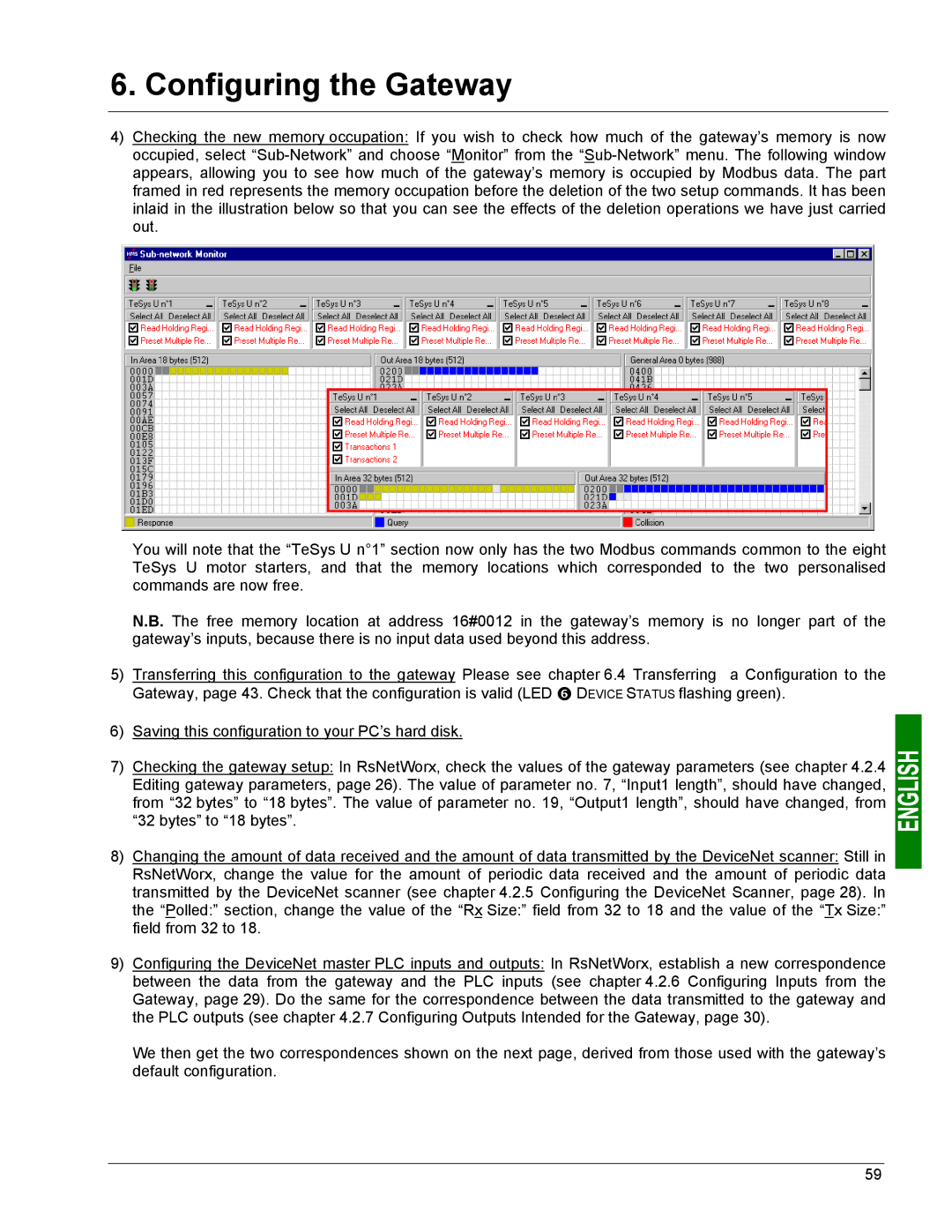
4)Checking the new memory occupation: If you wish to check how much of the gateway’s memory is now occupied, select
You will note that the “TeSys U n°1” section now only has the two Modbus commands common to the eight TeSys U motor starters, and that the memory locations which corresponded to the two personalised commands are now free.
N.B. The free memory location at address 16#0012 in the gateway’s memory is no longer part of the gateway’s inputs, because there is no input data used beyond this address.
5) Transferring this configuration to the gateway Please see chapter 6.4 Transferring a Configuration to the Gateway, page 43. Check that the configuration is valid (LED s DEVICE STATUS flashing green).
6)Saving this configuration to your PC’s hard disk.
7)Checking the gateway setup: In RsNetWorx, check the values of the gateway parameters (see chapter 4.2.4 Editing gateway parameters, page 26). The value of parameter no. 7, “Input1 length”, should have changed, from “32 bytes” to “18 bytes”. The value of parameter no. 19, “Output1 length”, should have changed, from “32 bytes” to “18 bytes”.
8)Changing the amount of data received and the amount of data transmitted by the DeviceNet scanner: Still in RsNetWorx, change the value for the amount of periodic data received and the amount of periodic data transmitted by the DeviceNet scanner (see chapter 4.2.5 Configuring the DeviceNet Scanner, page 28). In the “Polled:” section, change the value of the “Rx Size:” field from 32 to 18 and the value of the “Tx Size:” field from 32 to 18.
9)Configuring the DeviceNet master PLC inputs and outputs: In RsNetWorx, establish a new correspondence between the data from the gateway and the PLC inputs (see chapter 4.2.6 Configuring Inputs from the Gateway, page 29). Do the same for the correspondence between the data transmitted to the gateway and the PLC outputs (see chapter 4.2.7 Configuring Outputs Intended for the Gateway, page 30).
We then get the two correspondences shown on the next page, derived from those used with the gateway’s default configuration.
59