6. Configuring the Gateway
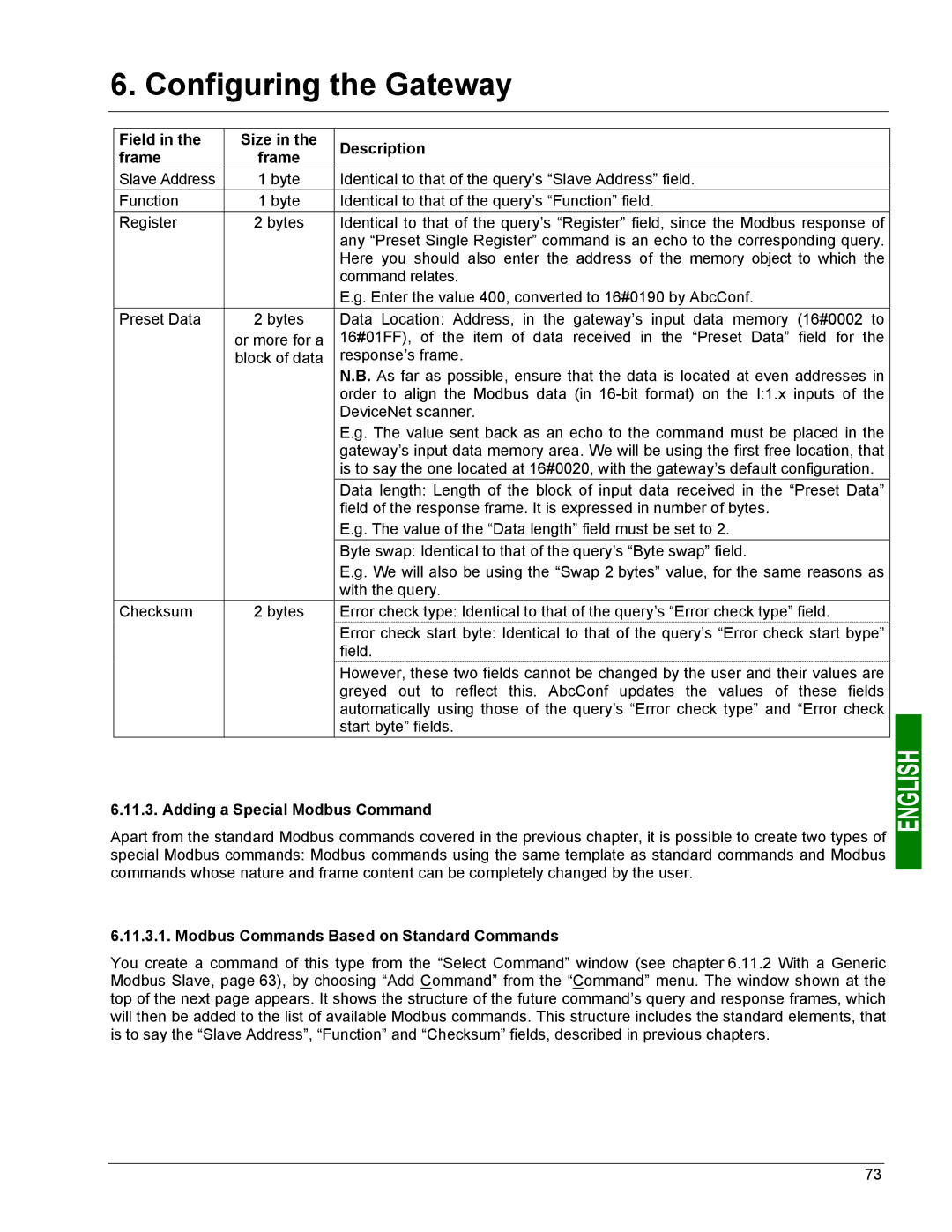
Field in the | Size in the | Description | |
frame | frame | ||
| |||
Slave Address | 1 byte | Identical to that of the query’s “Slave Address” field. | |
Function | 1 byte | Identical to that of the query’s “Function” field. | |
Register | 2 bytes | Identical to that of the query’s “Register” field, since the Modbus response of | |
|
| any “Preset Single Register” command is an echo to the corresponding query. | |
|
| Here you should also enter the address of the memory object to which the | |
|
| command relates. | |
|
| E.g. Enter the value 400, converted to 16#0190 by AbcConf. | |
Preset Data | 2 bytes | Data Location: Address, in the gateway’s input data memory (16#0002 to | |
| or more for a | 16#01FF), of the item of data received in the “Preset Data” field for the | |
| block of data | response’s frame. | |
|
| N.B. As far as possible, ensure that the data is located at even addresses in | |
|
| order to align the Modbus data (in | |
|
| DeviceNet scanner. | |
|
| E.g. The value sent back as an echo to the command must be placed in the | |
|
| gateway’s input data memory area. We will be using the first free location, that | |
|
| is to say the one located at 16#0020, with the gateway’s default configuration. | |
|
| Data length: Length of the block of input data received in the “Preset Data” | |
|
| field of the response frame. It is expressed in number of bytes. | |
|
| E.g. The value of the “Data length” field must be set to 2. | |
|
| Byte swap: Identical to that of the query’s “Byte swap” field. | |
|
| E.g. We will also be using the “Swap 2 bytes” value, for the same reasons as | |
|
| with the query. | |
Checksum | 2 bytes | Error check type: Identical to that of the query’s “Error check type” field. | |
|
| Error check start byte: Identical to that of the query’s “Error check start bype” | |
|
| field. | |
|
| However, these two fields cannot be changed by the user and their values are | |
|
| greyed out to reflect this. AbcConf updates the values of these fields | |
|
| automatically using those of the query’s “Error check type” and “Error check | |
|
| start byte” fields. |
6.11.3. Adding a Special Modbus Command
Apart from the standard Modbus commands covered in the previous chapter, it is possible to create two types of special Modbus commands: Modbus commands using the same template as standard commands and Modbus commands whose nature and frame content can be completely changed by the user.
6.11.3.1. Modbus Commands Based on Standard Commands
You create a command of this type from the “Select Command” window (see chapter 6.11.2 With a Generic Modbus Slave, page 63), by choosing “Add Command” from the “Command” menu. The window shown at the top of the next page appears. It shows the structure of the future command’s query and response frames, which will then be added to the list of available Modbus commands. This structure includes the standard elements, that is to say the “Slave Address”, “Function” and “Checksum” fields, described in previous chapters.
73