9. Appendix C: Practical Example (RSLogix 500)
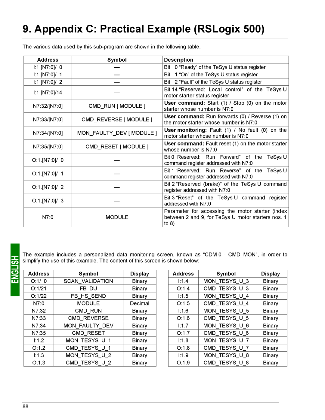
The various data used by this
Address |
| Symbol | Description |
|
| |
I:1.[N7:0]/ | 0 | — | Bit | 0 “Ready” of the TeSys U status register |
| |
I:1.[N7:0]/ | 1 | — | Bit | 1 “On” of the TeSys U status register |
| |
I:1.[N7:0]/ | 2 | — | Bit | 2 “Fault” of the TeSys U status register |
| |
I:1.[N7:0]/14 | — | Bit 14 “Reserved: Local control” of | the | TeSys U | ||
motor starter status register |
|
| ||||
|
|
|
|
| ||
N7:32/[N7:0] | CMD_RUN [ MODULE ] | User command: Start (1) / Stop (0) on the motor | ||||
starter whose number is N7:0 |
|
| ||||
|
|
|
|
| ||
N7:33/[N7:0] | CMD_REVERSE [ MODULE ] | User command: Run forwards (0) / Reverse (1) on | ||||
the motor starter whose number is N7:0 |
| |||||
|
|
|
| |||
N7:34/[N7:0] | MON_FAULTY_DEV [ MODULE ] | User monitoring: Fault (1) / No fault (0) on the | ||||
motor starter whose number is N7:0 |
|
| ||||
|
|
|
|
| ||
N7:35/[N7:0] | CMD_RESET [ MODULE ] | User command: Fault reset (1) on the motor starter | ||||
whose number is N7:0 |
|
| ||||
|
|
|
|
| ||
O:1.[N7:0]/ | 0 | — | Bit 0 “Reserved: Run Forward” of | the | TeSys U | |
command register addressed with N7:0 |
|
| ||||
|
|
|
|
| ||
O:1.[N7:0]/ | 1 | — | Bit 1 “Reserved: Run Reverse” of | the | TeSys U | |
command register addressed with N7:0 |
|
| ||||
|
|
|
|
| ||
O:1.[N7:0]/ | 2 | — | Bit 2 “Reserved (brake)” of the TeSys U command | |||
register addressed with N7:0 |
|
| ||||
|
|
|
|
| ||
O:1.[N7:0]/ | 3 | — | Bit 3 “Reset” of the TeSys U command | register | ||
addressed with N7:0 |
|
| ||||
|
|
|
|
| ||
|
|
| Parameter for accessing the motor starter (index | |||
N7:0 |
| MODULE | between 2 and 9, for TeSys U motor starters nos. 1 | |||
|
|
| to 8) |
|
|
|
The example includes a personalized data monitoring screen, known as “CDM 0 - CMD_MON”, in order to simplify the use of this example. The content of this screen is shown below:
Address | Symbol | Display |
O:1/ 0 | SCAN_VALIDATION | Binary |
O:1/21 | FB_DU | Binary |
O:1/22 | FB_HS_SEND | Binary |
N7:0 | MODULE | Decimal |
N7:32 | CMD_RUN | Binary |
N7:33 | CMD_REVERSE | Binary |
N7:34 | MON_FAULTY_DEV | Binary |
N7:35 | CMD_RESET | Binary |
I:1.2 | MON_TESYS_U_1 | Binary |
O:1.2 | CMD_TESYS_U_1 | Binary |
I:1.3 | MON_TESYS_U_2 | Binary |
O:1.3 | CMD_TESYS_U_2 | Binary |
Address | Symbol | Display |
I:1.4 | MON_TESYS_U_3 | Binary |
O:1.4 | CMD_TESYS_U_3 | Binary |
I:1.5 | MON_TESYS_U_4 | Binary |
O:1.5 | CMD_TESYS_U_4 | Binary |
I:1.6 | MON_TESYS_U_5 | Binary |
O:1.6 | CMD_TESYS_U_5 | Binary |
I:1.7 | MON_TESYS_U_6 | Binary |
O:1.7 | CMD_TESYS_U_6 | Binary |
I:1.8 | MON_TESYS_U_7 | Binary |
O:1.8 | CMD_TESYS_U_7 | Binary |
I:1.9 | MON_TESYS_U_8 | Binary |
O:1.9 | CMD_TESYS_U_8 | Binary |
88
