9. Appendix C: Practical Example (RSLogix 500)
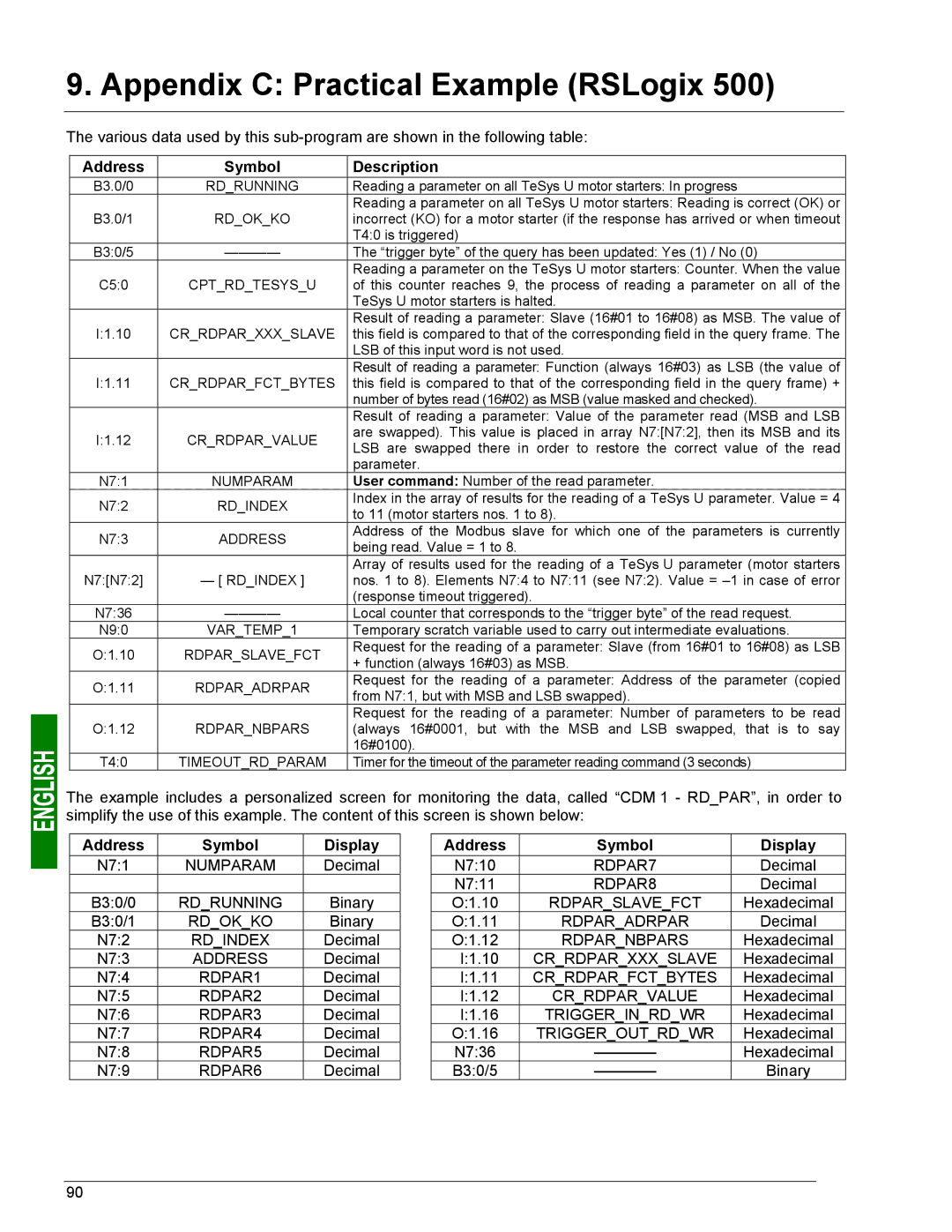
The various data used by this
Address | Symbol | Description | |
B3.0/0 | RD_RUNNING | Reading a parameter on all TeSys U motor starters: In progress | |
|
| Reading a parameter on all TeSys U motor starters: Reading is correct (OK) or | |
B3.0/1 | RD_OK_KO | incorrect (KO) for a motor starter (if the response has arrived or when timeout | |
|
| T4:0 is triggered) | |
B3:0/5 | The “trigger byte” of the query has been updated: Yes (1) / No (0) | ||
|
| Reading a parameter on the TeSys U motor starters: Counter. When the value | |
C5:0 | CPT_RD_TESYS_U | of this counter reaches 9, the process of reading a parameter on all of the | |
|
| TeSys U motor starters is halted. | |
|
| Result of reading a parameter: Slave (16#01 to 16#08) as MSB. The value of | |
I:1.10 | CR_RDPAR_XXX_SLAVE | this field is compared to that of the corresponding field in the query frame. The | |
|
| LSB of this input word is not used. | |
|
| Result of reading a parameter: Function (always 16#03) as LSB (the value of | |
I:1.11 | CR_RDPAR_FCT_BYTES | this field is compared to that of the corresponding field in the query frame) + | |
|
| number of bytes read (16#02) as MSB (value masked and checked). | |
|
| Result of reading a parameter: Value of the parameter read (MSB and LSB | |
I:1.12 | CR_RDPAR_VALUE | are swapped). This value is placed in array N7:[N7:2], then its MSB and its | |
LSB are swapped there in order to restore the correct value of the read | |||
|
| ||
|
| parameter. | |
N7:1 | NUMPARAM | User command: Number of the read parameter. | |
N7:2 | RD_INDEX | Index in the array of results for the reading of a TeSys U parameter. Value = 4 | |
to 11 (motor starters nos. 1 to 8). | |||
|
| ||
N7:3 | ADDRESS | Address of the Modbus slave for which one of the parameters is currently | |
being read. Value = 1 to 8. | |||
|
| ||
|
| Array of results used for the reading of a TeSys U parameter (motor starters | |
N7:[N7:2] | — [ RD_INDEX ] | nos. 1 to 8). Elements N7:4 to N7:11 (see N7:2). Value = | |
|
| (response timeout triggered). | |
N7:36 | Local counter that corresponds to the “trigger byte” of the read request. | ||
N9:0 | VAR_TEMP_1 | Temporary scratch variable used to carry out intermediate evaluations. | |
O:1.10 | RDPAR_SLAVE_FCT | Request for the reading of a parameter: Slave (from 16#01 to 16#08) as LSB | |
+ function (always 16#03) as MSB. | |||
|
| ||
O:1.11 | RDPAR_ADRPAR | Request for the reading of a parameter: Address of the parameter (copied | |
from N7:1, but with MSB and LSB swapped). | |||
|
| ||
|
| Request for the reading of a parameter: Number of parameters to be read | |
O:1.12 | RDPAR_NBPARS | (always 16#0001, but with the MSB and LSB swapped, that is to say | |
|
| 16#0100). | |
T4:0 | TIMEOUT_RD_PARAM | Timer for the timeout of the parameter reading command (3 seconds) |
The example includes a personalized screen for monitoring the data, called “CDM 1 - RD_PAR”, in order to simplify the use of this example. The content of this screen is shown below:
Address | Symbol | Display |
N7:1 | NUMPARAM | Decimal |
|
|
|
B3:0/0 | RD_RUNNING | Binary |
B3:0/1 | RD_OK_KO | Binary |
N7:2 | RD_INDEX | Decimal |
N7:3 | ADDRESS | Decimal |
N7:4 | RDPAR1 | Decimal |
N7:5 | RDPAR2 | Decimal |
N7:6 | RDPAR3 | Decimal |
N7:7 | RDPAR4 | Decimal |
N7:8 | RDPAR5 | Decimal |
N7:9 | RDPAR6 | Decimal |
Address | Symbol | Display |
N7:10 | RDPAR7 | Decimal |
N7:11 | RDPAR8 | Decimal |
O:1.10 | RDPAR_SLAVE_FCT | Hexadecimal |
O:1.11 | RDPAR_ADRPAR | Decimal |
O:1.12 | RDPAR_NBPARS | Hexadecimal |
I:1.10 | CR_RDPAR_XXX_SLAVE | Hexadecimal |
I:1.11 | CR_RDPAR_FCT_BYTES | Hexadecimal |
I:1.12 | CR_RDPAR_VALUE | Hexadecimal |
I:1.16 | TRIGGER_IN_RD_WR | Hexadecimal |
O:1.16 | TRIGGER_OUT_RD_WR | Hexadecimal |
N7:36 | Hexadecimal | |
B3:0/5 | Binary |
90
