2. Hardware Implementation of the LUFP9 Gateway
2) Cables: |
|
VW3 A8 306 R•• Modbus cable | Shielded cable with a male RJ45 connector at each |
(“star” topology / “bus” topology with tap boxes) | end. |
VW3 A68 306 Modbus cable | Shielded cable with a male RJ45 connector and a |
(“bus” topology with tap boxes) | male |
| a Modbus subscriber (slave or master) to a |
| TSXSCA62 or TSXCA50 box. |
Shielded double twisted pair Modbus cable | Bare cable (without connectors) used to make up the |
(“bus” topology with branch boxes) | main section of the Modbus network. There are three |
| items available: TSXCSA100 (100 m), TSXCSA200 |
| (200 m), and TSXCSA500 (500 m). |
2.6. Connecting the LUFP9 gateway to the DeviceNet network
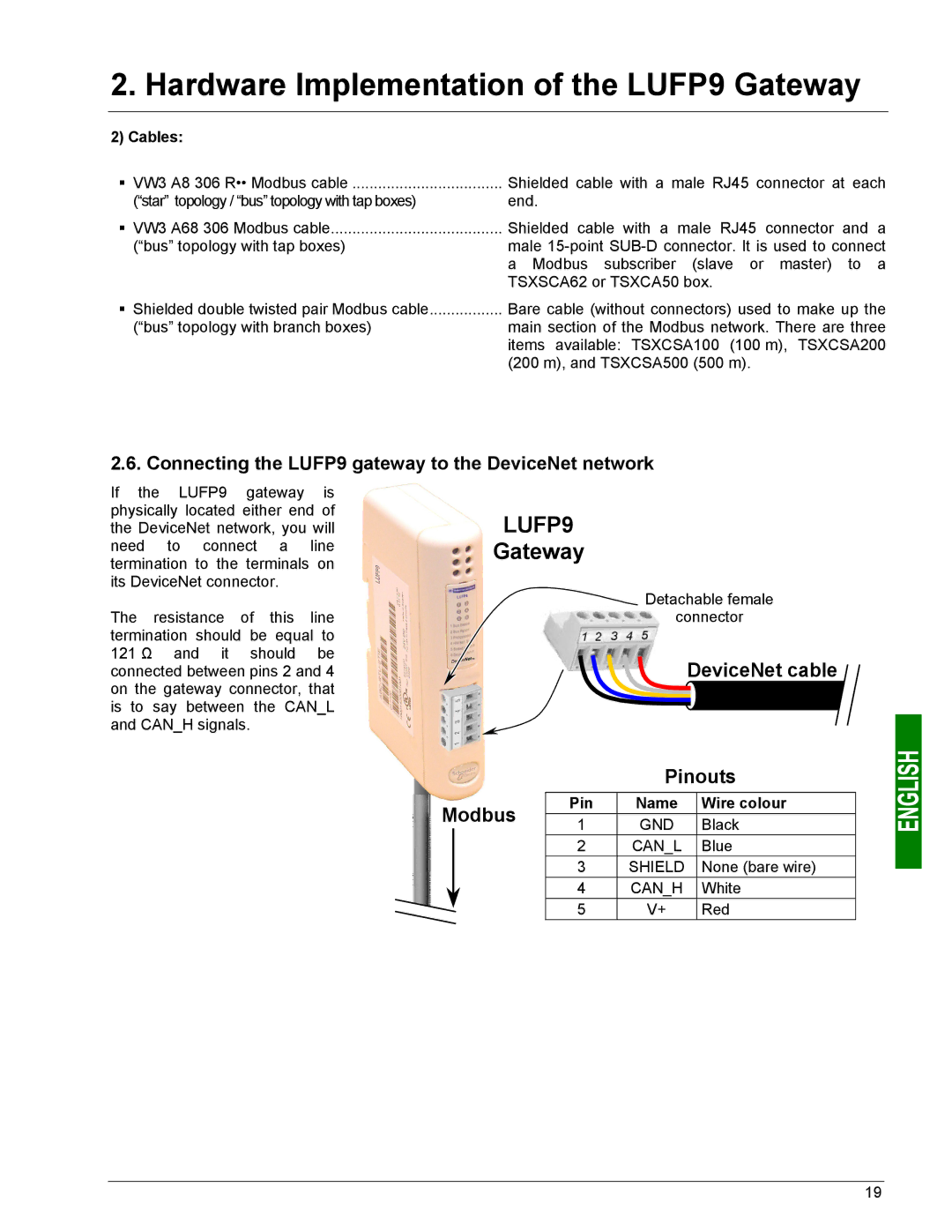
If the LUFP9 gateway is physically located either end of the DeviceNet network, you will need to connect a line termination to the terminals on its DeviceNet connector.
The resistance of this line termination should be equal to 121 Ω and it should be connected between pins 2 and 4 on the gateway connector, that is to say between the CAN_L and CAN_H signals.
LUFP9
Gateway
Detachable female
connector
DeviceNet cable
|
|
| Pinouts | ||
Modbus | Pin | Name | Wire colour | ||
1 | GND | Black | |||
|
| ||||
|
| 2 | CAN_L | Blue | |
|
| 3 | SHIELD | None (bare wire) | |
|
| 4 | CAN_H | White | |
|
|
|
|
| |
|
| 5 | V+ | Red | |
19
