6. Configuring the Gateway
6.8.2. Replacing an Output Periodic Data Element
E.g. “TeSys U n°6” motor starter. We are trying to replace the control of the “Command Register” (address 704 = 16#02C0) with the control of the “2nd Command Register” (address 705 = 16#02C1).
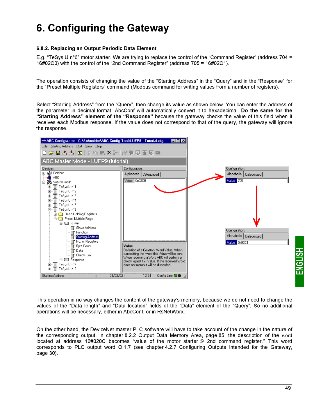
The operation consists of changing the value of the “Starting Address” in the “Query” and in the “Response” for the “Preset Multiple Registers” command (Modbus command for writing values from a number of registers).
Select “Starting Address” from the “Query”, then change its value as shown below. You can enter the address of the parameter in decimal format. AbcConf will automatically convert it to hexadecimal. Do the same for the “Starting Address” element of the “Response” because the gateway checks the value of this field when it receives each Modbus response. If the value does not correspond to that of the query, the gateway will ignore the response.
This operation in no way changes the content of the gateway’s memory, because we do not need to change the values of the “Data length” and “Data location” fields of the “Data” element of the “Query”. So no additional operations will be necessary, either in AbcConf, or in RsNetWorx.
On the other hand, the DeviceNet master PLC software will have to take account of the change in the nature of the corresponding output. In chapter 8.2.2 Output Data Memory Area, page 85, the description of the word located at address 16#020C becomes “value of the motor starter h 2nd command register.” This word corresponds to PLC output word O:1.7 (see chapter 4.2.7 Configuring Outputs Intended for the Gateway, page 30).
49