7. Appendix A: Technical Characteristics
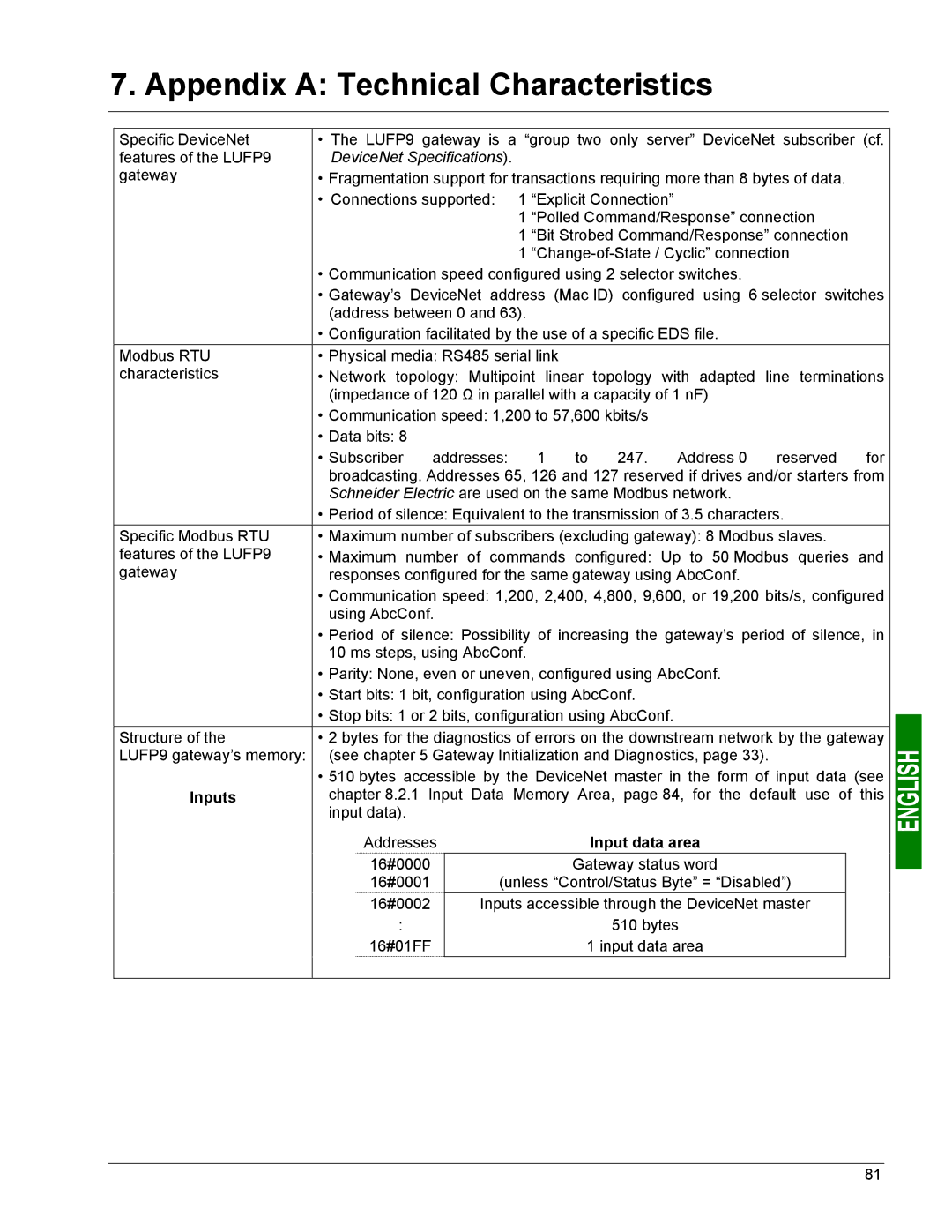
Specific DeviceNet | • The LUFP9 gateway is a “group two only server” DeviceNet subscriber (cf. | |||||||||||
features of the LUFP9 | DeviceNet Specifications). |
|
|
|
|
|
|
| ||||
gateway | • Fragmentation support for transactions requiring more than 8 bytes of data. |
| ||||||||||
| • Connections supported: | 1 “Explicit Connection” |
|
|
|
| ||||||
|
|
|
|
|
| 1 “Polled Command/Response” connection |
| |||||
|
|
|
|
|
| 1 “Bit Strobed Command/Response” connection |
| |||||
|
|
|
|
|
| 1 |
| |||||
| • Communication speed configured using 2 selector switches. |
|
|
| ||||||||
| • Gateway’s DeviceNet address (Mac ID) configured using 6 selector switches | |||||||||||
| (address between 0 and 63). |
|
|
|
|
|
| |||||
| • Configuration facilitated by the use of a specific EDS file. |
|
|
| ||||||||
Modbus RTU | • Physical media: RS485 serial link |
|
|
|
|
|
| |||||
characteristics | • Network topology: Multipoint linear topology with adapted line terminations | |||||||||||
| (impedance of 120 Ω in parallel with a capacity of 1 nF) |
|
|
| ||||||||
| • Communication speed: 1,200 to 57,600 kbits/s |
|
|
|
| |||||||
| • Data bits: 8 |
|
|
|
|
|
|
|
|
|
|
|
| • Subscriber | addresses: | 1 | to | 247. | Address 0 | reserved | for | ||||
| broadcasting. Addresses 65, 126 and 127 reserved if drives and/or starters from | |||||||||||
| Schneider Electric are used on the same Modbus network. |
|
|
| ||||||||
| • Period of silence: Equivalent to the transmission of 3.5 characters. |
| ||||||||||
Specific Modbus RTU | • Maximum number of subscribers (excluding gateway): 8 Modbus slaves. |
| ||||||||||
features of the LUFP9 | • Maximum number of commands configured: Up to 50 Modbus queries and | |||||||||||
gateway | responses configured for the same gateway using AbcConf. |
|
|
| ||||||||
| • Communication speed: 1,200, 2,400, 4,800, 9,600, or 19,200 bits/s, configured | |||||||||||
| using AbcConf. |
|
|
|
|
|
|
|
| |||
| • Period of silence: Possibility of increasing the gateway’s period of silence, in | |||||||||||
| 10 ms steps, using AbcConf. |
|
|
|
|
|
| |||||
| • Parity: None, even or uneven, configured using AbcConf. |
|
|
| ||||||||
| • Start bits: 1 bit, configuration using AbcConf. |
|
|
|
| |||||||
| • Stop bits: 1 or 2 bits, configuration using AbcConf. |
|
|
|
| |||||||
Structure of the | • 2 bytes for the diagnostics of errors on the downstream network by the gateway | |||||||||||
LUFP9 gateway’s memory: | (see chapter 5 Gateway Initialization and Diagnostics, page 33). |
| ||||||||||
| • 510 bytes accessible by the DeviceNet master in the form of input data (see | |||||||||||
Inputs | chapter 8.2.1 | Input | Data | Memory | Area, | page 84, for the | default use of | this | ||||
| input data). |
|
|
|
|
|
|
|
|
|
|
|
| Addresses |
|
| Input data area |
|
|
| |||||
| 16#0000 |
|
|
|
| Gateway status word |
|
|
| |||
| 16#0001 |
|
| (unless “Control/Status Byte” = “Disabled”) |
|
| ||||||
| 16#0002 |
|
| Inputs accessible through the DeviceNet master |
|
| ||||||
| : |
|
|
|
|
| 510 bytes |
|
|
| ||
| 16#01FF |
|
|
| 1 input data area |
|
|
| ||||
|
|
|
|
|
|
|
|
|
|
|
|
|
81
