Manuals
/
Seiko Instruments
/
Household Appliance
/
Heat Pump
Seiko Instruments
MT-17E-003-D
instruction manual
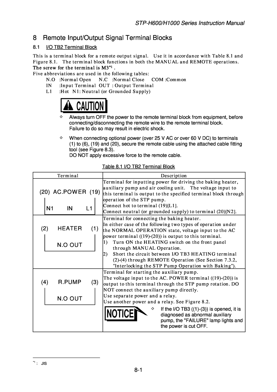
Remote Input/Output Signal Terminal Blocks
Models:
MT-17E-003-D
1
75
124
124
Download
124 pages
22.02 Kb
72
73
74
75
76
77
78
79
Troubleshooting
Install
Symbols
Warranty
Maintenance
Symptom
16.3Accessories
6Connector Caution Label
6.1.8Abnormal Battery Voltage
5.3Start Procedures
Page 75
Image 75
Page 74
Page 76
Page 75
Image 75
Page 74
Page 76
Contents
STP-H600/H1000Series
Third Edition-d
MT-17E-003-D
SAFETY PRECAUTIONS
Symbols
Death or Serious Personal Injury
Operators can burn hands
Connect or disconnect cables
DO NOT put foreign objects into the STP pump. Doing so may result in product damage
EC Electromagnetic Compatibility Directive
INTRODUCTION
APPLIED STANDARDS
Applied Directives EC Machinery Directive
Sales Office Japan
PRECAUTIONS
REQUEST
Seiko Instruments Inc
LIMITED WARRANTY
16Overhaul and replacement of maintenance parts
indication “WARNING” message on the LCD display
Touch down bearing Heater
TABLE OF CONTENTS
7 Gas Suction, Cooling and Baking the STP Pump
12 Maintenance and Inspection
TABLES
FIGURES
1 Precautions for Safe Operation of the STP Pump
1.4Labels
1.3Inspection Precautions
3Heavy Product Caution Label
6Connector Caution Label
200~240V
Tuning must be performed
浮上調整を行う場合は弊社 のトレーニングまたは許可を 受けてください。
2 Unpacking
2.2Unpacking the STP Control Unit
3 Installation of the STP pump
3.1Name and Function of Each Part
NEVER remove it
Figure 3.1 Configuration of the STP Pump
9 Temperature Sensor Connector Optional Accessory
6 Cooling Water Port 3 STP Connector
4 Motor Connector 8 Ground Terminal
3.2Precautions Before Installation
3.2.2Installation Area
3.3How to Install the STP Pump
3.3.1Cleaning the Seal
3.3.2STP Pump Installation Positions
Figure 3.3 STP Pump Installation Positions
Upside-down Horizontal STP Pump Slanted Vertical
24.1
Size of bolt
Tightening torque of bolt Nm
12.0
Secure the base
a When the base is not secured
When securing the inlet port with bolts
Recommended fitting bolt for flange
4 or more
Size of Flange
Number of Claw Clamps
ISO 160 or less
Vacuum Equipment
3.3.4Vacuum Piping
1Piping at the Inlet Port Flange
3.3.5Connecting the Emergency Vent. Valve
3.3.7Connecting the Ground Cable
4 Installation of the STP Control Unit
4.1Name and Function of Each Part
4.1.1Front Panel
8OVER TEMPERATURE Lamp red LED
Figure 4.1 STP Control Unit Front Panel
4.1.2Rear Panel
Figure 4.2 STP Control Unit Rear Panel
4.1.3Inside of the STP Control Unit
Figure 4.3 Inside of the STP Control Unit
2530
4.2.1Operating Environment
4.2Precautions Before Installation
4.2.2Installation Area
4-10
part Secure with screw Support Angle
STP Control Unit Side
4.4.1Name and Dimensions of Each Cable
Figure 4.6 External Dimensions of Each Cable
4.4Cable Connection
Figure 4.7 External Dimensions of he Power Cable
4.4.2How to Connect the Cables
STP-H600/H1000 Series
Table 4.1 Connecting Primary Power Cable
Figure 4.8 How to Secure Primary Power Cable
Magnified TB1 TB1 Cover Ground Cable for Cover
Cable Fitting Tool
5 How to Start/Stop the STP Pump
5.3Start Procedures
5.5Manual Operation
REMOTE
Select one which fits your vacuum equipment
5.5.1Powering ON
5.5.5Powering OFF
5.6.3Starting the STP Pump After Stopping
5.6.1Powering ON
5.6Remote Operation
5.6.2Starting/Stopping the STP Pump
5.6.4Powering OFF
6.1Safety Functions 6.1.1Power Failure
Operation after a Power Recovery
6.1.5Overheating Inside the STP pump
6.1.2Abnormal State of Magnetic Bearing
6.1.3Excessive Vibration
6.1.4Inverter Overload
6.1.8Abnormal Battery Voltage
6.2Restarting after Any Safety Function Operates
3Other Cases
6.3Operation of the Emergency Vent. Valve
Abnormality
Abnormality
7 Gas Suction, Cooling and Baking the STP Pump
7.2Cooling the STP Pump
7.2.2Air Cooling Method
7.3Baking the STP Pump
This label is attached to the baking heater
Failure to do so may result in electric shock
8 Remote Input/Output Signal Terminal Blocks
N.O OUT
I/O TB2 Remote Output Signal Terminal Block
Table 8.3 Rated Contacts for Relays CR5 and
Page
L.VALVE
DC I/O TB3
START IN
STOP IN
The screw for the terminal is M4*1
DO NOT apply excessive force to the remote cable
START/STOP IN
8.4START/STOP TB6 Terminal Block
The screw for the terminal is M4*1
9 Internal Battery
Figure 9.2 Allowable Shelf Life of the Internal
Figure 9.1 Life of the Internal Battery
9.3How to Charge the Internal Battery
Battery
9.4BATTERY NG Lamp
9.5How to Replace the Internal Battery
2Disconnect battery internal connector
Affix this label to the front panel
5 Figure 9.1 How to Replace the Internal Battery
2 8 1 4 10 3 5 11
9.6How to Dispose of the Internal Battery
10 External Battery
10.2Installation of the External Battery
10.3How to Charge the External Battery
11 Operation Principle of the STP Pump
3 Radial sensor 4 Radial electromagnet
7 Touch down bearing 8 Touch down bearing
1 Rotor blade 2 Stator blade
4 Radial electromagnet 3 Radial sensor
12 Maintenance and Inspection
12.3Replacing the Fuses
12.4Inspecting for Deposit
12.5Overhaul
12.6Transporting for Repair or Overhaul
13.1The STP Pump
13 Storage
13.2The STP Control Unit
13.3Restarting Precautions
14 Disposal
14.3The Battery
15 Troubleshooting
3Other Cases
15.4Abnormalities While the STP Pump is Rotating
Symptom
The lamp is being lit
Countermeasures
PROCEDU
Lamp Being Lit
Probable Causes
No.4
No.6
16 Specifications and Accessories
16.1Specifications for the STP Pump
16-1
16.216.2 Specifications for the STP Control Unit
Page
16-4
16.3Accessories
Table 16.3 Accessories
16.4Recommended Spare Parts
STP-H600/H1000
Unit
SEIKO SEIKI
Instruction
Manual
Install pump securely
caution with Handle
performed be should Tuning
SAFETY INSTRUCTIONS
SEIKO SEIKI
Hot surface
やけどします。
触らないでく
ださい。
Name
STP PUMP PROBLEM CHECK SHEET
Seiko Seiki Comment
Date
Length
Mass
Pressure
Sales Office Japan
Top
Page
Image
Contents