|
|
|
|
|
|
|
|
|
|
|
|
|
|
|
|
|
|
|
|
|
|
|
|
|
|
|
|
|
| TMS380C26 | |||
|
|
|
|
|
|
|
|
|
|
|
|
|
|
|
|
|
|
|
|
|
|
|
|
| NETWORK COMMPROCESSOR | ||||||||
|
|
|
|
|
|
|
|
|
|
|
|
|
|
|
|
|
|
|
|
|
|
|
|
| SPWS010A±APRIL 1992±REVISED MARCH 1993 | ||||||||
|
|
|
|
|
|
|
|
|
|
|
|
|
|
|
|
|
|
|
|
|
|
|
|
|
|
|
|
| |||||
|
|
|
|
|
|
|
|
|
|
|
|
|
|
|
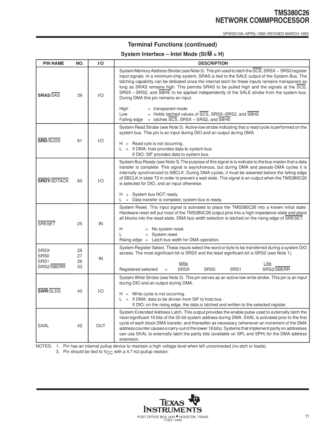
| Terminal Functions (continued) |
|
|
|
|
|
|
|
| |||||||||
|
|
|
|
|
|
|
|
|
|
|
|
|
|
|
|
|
|
| = H) |
|
|
|
|
|
|
|
| ||||||
|
|
|
|
|
|
|
|
|
|
|
|
|
|
| System Interface ± Intel Mode (SI/M |
|
|
|
|
|
|
|
| ||||||||||
|
|
|
|
|
|
|
|
|
|
|
|
|
|
|
|
|
|
|
|
|
|
|
|
|
|
|
|
|
|
|
| ||
| PIN NAME | NO. | I/O |
|
|
|
|
|
| DESCRIPTION |
|
|
|
|
|
|
|
| |||||||||||||||
|
|
|
|
|
|
|
|
|
|
|
|
|
|
|
|
|
|
|
|
|
| ||||||||||||
|
|
|
|
|
|
|
|
|
|
|
|
|
|
| System Memory Address Strobe (see Note 3). This pin used to latch the |
|
| SRSX ± SRS2 register | |||||||||||||||
|
|
|
|
|
|
|
|
|
|
|
|
|
|
| SCS, | ||||||||||||||||||
|
|
|
|
|
|
|
|
|
|
|
|
|
|
| input signals. In a | ||||||||||||||||||
|
|
|
|
|
|
|
|
|
|
|
|
|
|
| latching capability can be defeated since the internal latch for these inputs remains transparent as | ||||||||||||||||||
|
|
|
|
|
|
|
|
|
|
|
|
|
|
| long as SRAS remains high. This permits SRAS to be pulled high and the signals at the SCS, | ||||||||||||||||||
|
|
|
|
|
|
|
|
|
|
|
|
|
|
| SRSX ± SRS2, and SBHE to be applied independently of the SALE strobe from the system bus. | ||||||||||||||||||
| SRAS/SAS | 39 | I/O | ||||||||||||||||||||||||||||||
| During DMA this pin remains an input. |
|
|
|
|
|
|
|
|
|
|
|
|
| |||||||||||||||||||
|
|
|
|
|
|
|
|
|
|
|
|
|
|
|
|
|
|
|
|
|
|
|
|
|
|
|
| ||||||
|
|
|
|
|
|
|
|
|
|
|
|
|
|
| High |
| = | transparent mode |
|
|
|
|
|
|
|
|
|
|
|
|
| ||
|
|
|
|
|
|
|
|
|
|
|
|
|
|
| Low |
| = Holds latched values of | SCS, | SRSX±SRS2, and | SBHE |
|
|
|
|
| ||||||||
|
|
|
|
|
|
|
|
|
|
|
|
|
|
| Falling edge | = | latches SCS, SRSX ± SRS2, and SBHE |
|
|
|
| ||||||||||||
|
|
|
|
|
|
|
|
|
|
|
|
|
|
|
|
|
| ||||||||||||||||
|
|
|
|
|
|
|
|
|
|
|
|
|
|
| System Read Strobe (see Note 3). | ||||||||||||||||||
|
|
|
|
|
|
|
|
|
|
|
|
|
|
| system bus. This pin is an input during DIO and an output during DMA. |
|
|
|
| ||||||||||||||
|
|
|
|
|
|
|
|
|
|
| 61 | I/O |
|
|
|
|
|
|
|
|
|
|
|
|
|
|
|
|
|
|
| ||
| SRD |
|
| /SUDS |
|
|
|
| H | = | Read cyle is not occurring. |
|
|
|
|
|
|
|
|
|
|
|
|
| |||||||||
|
|
|
|
|
|
|
|
|
|
|
|
|
|
|
|
|
|
|
|
|
|
|
|
|
|
|
| ||||||
|
|
|
|
|
|
|
|
|
|
|
|
|
|
| L | = | If DMA: host provides data to system bus. |
|
|
|
|
|
|
|
| ||||||||
|
|
|
|
|
|
|
|
|
|
|
|
|
|
|
|
| If DIO: SIF provides data to system bus. |
|
|
|
|
|
|
|
| ||||||||
|
|
|
|
|
|
|
|
|
|
|
|
|
|
|
|
|
| ||||||||||||||||
|
|
|
|
|
|
|
|
|
|
|
|
|
|
| System Bus Ready (see Note 3).The purpose of this signal is to indicate to the bus master that a data | ||||||||||||||||||
|
|
|
|
|
|
|
|
|
|
|
|
|
|
| transfer is complete. This signal is asynchonous, but during DMA and | ||||||||||||||||||
|
|
|
|
|
|
|
|
|
|
|
|
|
|
| internally synchronized to SBCLK. During DMA cycles, it must be asserted before the falling edge | ||||||||||||||||||
|
|
|
|
|
|
|
|
|
|
|
|
|
|
| of SBCLK in state T2 in order to prevent a wait state. This signal is an output when the TMS380C26 | ||||||||||||||||||
| SRDY/SDTACK | 60 | I/O | ||||||||||||||||||||||||||||||
| is selected for DIO, and an input otherwise. |
|
|
|
|
|
|
|
| ||||||||||||||||||||||||
|
|
|
|
|
|
|
|
|
|
|
|
|
|
|
|
|
|
|
|
|
|
| |||||||||||
|
|
|
|
|
|
|
|
|
|
|
|
|
|
| H | = | System bus NOT ready. |
|
|
|
|
|
|
|
|
|
|
|
|
| |||
|
|
|
|
|
|
|
|
|
|
|
|
|
|
| L | = | Data transfer is complete; system bus is ready. |
|
|
|
|
|
|
|
| ||||||||
|
|
|
|
|
|
|
|
|
|
|
|
|
|
|
|
|
| ||||||||||||||||
|
|
|
|
|
|
|
|
|
|
|
|
|
|
| System Reset. This input signal is activated to place the TMS380C26 into a known initial state. | ||||||||||||||||||
|
|
|
|
|
|
|
|
|
|
|
|
|
|
| Hardware reset will put most of the TMS380C26 output pins into a | ||||||||||||||||||
|
|
|
|
|
|
|
|
|
|
|
|
|
|
| all blocks into the reset state. DMA bus width selection is latched on the rising edge of SRESET. | ||||||||||||||||||
| SRESET |
|
|
| 25 | IN |
|
|
|
|
|
|
|
|
|
|
|
|
|
|
|
|
|
|
| ||||||||
|
|
|
|
|
|
|
|
|
|
|
|
|
|
| H |
|
| = | No system reset. |
|
|
|
|
|
|
|
|
|
|
|
|
| |
|
|
|
|
|
|
|
|
|
|
|
|
|
|
| L |
|
| = | System reset. |
|
|
|
|
|
|
|
|
|
|
|
|
| |
|
|
|
|
|
|
|
|
|
|
|
|
|
|
| Rising edge | = | Latch bus width for DMA operation. |
|
|
|
|
|
|
|
| ||||||||
|
|
|
|
|
|
|
|
|
|
|
|
|
|
|
| ||||||||||||||||||
| SRSX | 28 |
| System Register Select. These inputs select the word or byte to be transferred during a system DIO | |||||||||||||||||||||||||||||
|
| access. The most significant bit is SRSX and the least significant bit is SRS2 (see Note 1). | |||||||||||||||||||||||||||||||
| SRS0 | 27 |
| ||||||||||||||||||||||||||||||
| IN |
|
|
|
|
|
|
|
|
|
|
|
|
|
|
|
|
|
|
| |||||||||||||
| SRS1 |
|
| 26 |
|
|
|
|
|
|
|
|
|
|
|
|
|
|
|
|
|
|
| ||||||||||
|
|
|
|
|
|
| MSb |
|
|
|
|
|
|
|
|
| LSb |
|
| ||||||||||||||
| SRS2/SBERR | 33 |
|
|
|
|
|
|
|
|
|
|
|
|
|
|
| ||||||||||||||||
|
| Registered selected = | SRSX |
| SRS0 | SRS1 | SRS2/SBERR | ||||||||||||||||||||||||||
|
|
|
|
|
|
|
|
|
|
|
|
|
|
|
| ||||||||||||||||||
|
|
|
|
|
|
|
|
|
|
|
|
|
|
|
| ||||||||||||||||||
|
|
|
|
|
|
|
|
|
|
|
|
|
|
| System Write Strobe (see Note 3). This pin serves as an | ||||||||||||||||||
|
|
|
|
|
|
|
|
|
|
|
|
|
|
| during DIO and an output during DMA. |
|
|
|
|
|
|
|
|
|
|
|
|
| |||||
|
|
|
| 40 | I/O |
|
|
|
|
|
|
|
|
|
|
|
|
|
|
|
|
|
|
| |||||||||
| SWR |
| /SLDS |
| H | = | Write cycle is not occurring. |
|
|
|
|
|
|
|
|
|
|
|
|
| |||||||||||||
|
|
|
|
|
|
|
|
|
|
|
|
|
|
|
|
|
|
|
|
|
|
|
|
|
|
|
| ||||||
|
|
|
|
|
|
|
|
|
|
|
|
|
|
| L | = | If DMA: data to be drivien from SIF to host bus. |
|
|
|
|
|
|
|
| ||||||||
|
|
|
|
|
|
|
|
|
|
|
|
|
|
|
|
| If DIO: on the rising edge, the data is latched and written to the selected register. | ||||||||||||||||
|
|
|
|
|
|
|
|
|
|
|
|
|
|
|
| ||||||||||||||||||
|
|
|
|
|
|
|
|
|
|
|
|
|
|
| System Extended Address Latch. This output provides the enable pulse used to externally latch the | ||||||||||||||||||
|
|
|
|
|
|
|
|
|
|
|
|
|
|
| most significant 16 bits of the | ||||||||||||||||||
| SXAL | 42 | OUT | cycle of each block DMA transfer, and thereafter as necessary (whenever an increment of the DMA | |||||||||||||||||||||||||||||
| address counter causes a | ||||||||||||||||||||||||||||||||
|
|
|
|
|
|
|
|
|
|
|
|
|
|
| |||||||||||||||||||
|
|
|
|
|
|
|
|
|
|
|
|
|
|
| can use SXAL to externally latch the parity bits (available on SPL and SPH) for the DMA address | ||||||||||||||||||
|
|
|
|
|
|
|
|
|
|
|
|
|
|
| extension. |
|
|
|
|
|
|
|
|
|
|
|
|
|
|
|
| ||
NOTES: 1. Pin has an internal pullup device to maintain a high voltage level when left unconnected (no etch or loads). 3. Pin should be tied to VCC with a
POST OFFICE BOX 1443 •HOUSTON, TEXAS | 11 |
77251±1443 |
|