|
|
|
|
|
|
|
|
|
|
|
|
| TMS380C26 | |
|
|
|
|
|
|
|
|
|
|
|
|
| NETWORK COMMPROCESSOR | |
|
|
|
|
|
|
|
|
|
|
|
|
| SPWS010A±APRIL 1992±REVISED MARCH 1993 | |
|
|
|
|
|
|
|
|
|
|
|
|
|
|
|
|
|
|
|
|
|
|
|
|
|
|
|
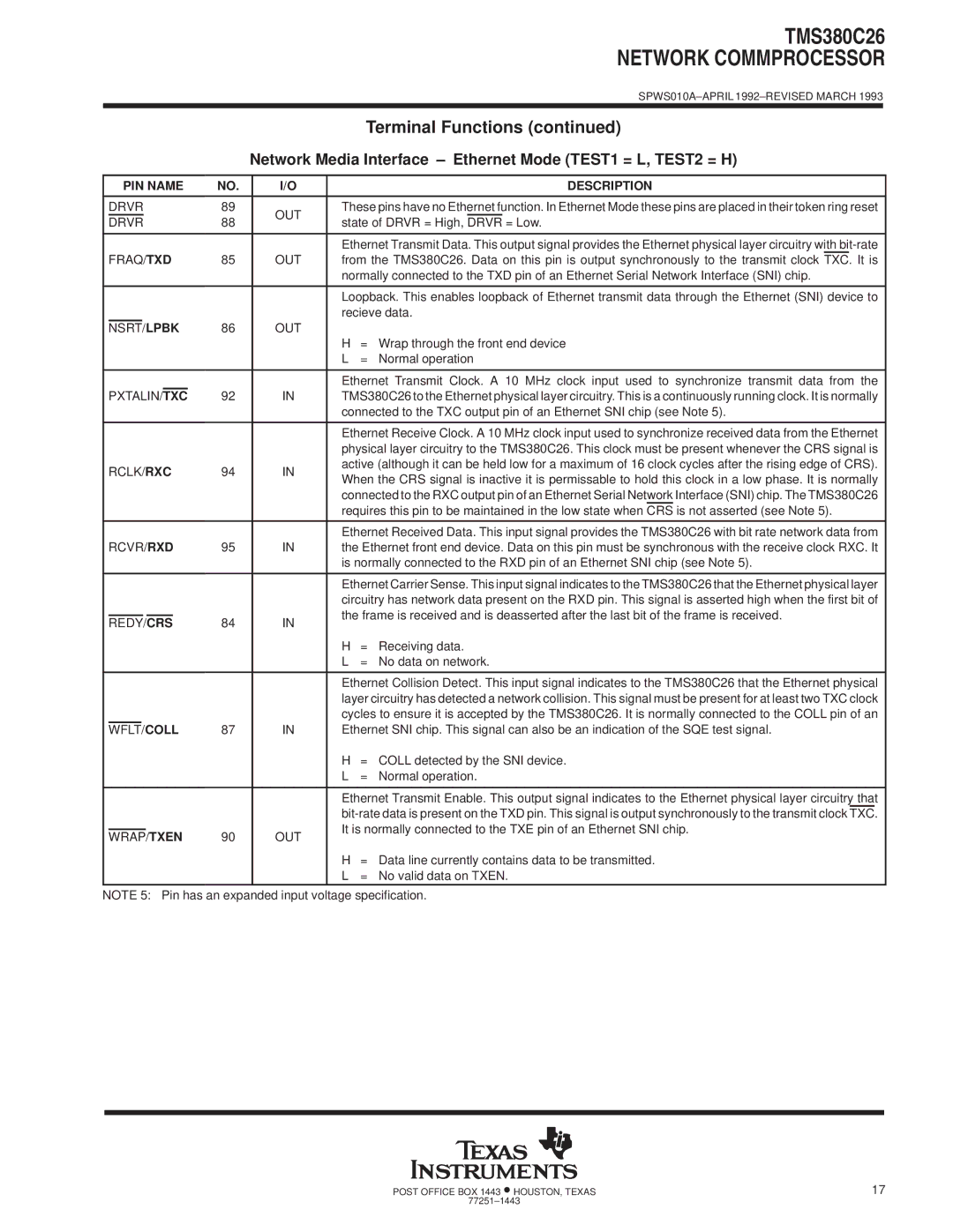
| Terminal Functions (continued) | |
|
|
|
|
|
|
|
|
|
| Network Media Interface ± Ethernet Mode (TEST1 = L, TEST2 = H) | ||||
|
|
|
|
|
|
|
|
|
|
|
|
|
| |
| PIN NAME | NO. |
| I/O |
| DESCRIPTION | ||||||||
|
|
|
|
|
|
|
|
|
|
|
|
| ||
| DRVR | 89 |
| OUT | These pins have no Ethernet function. In Ethernet Mode these pins are placed in their token ring reset | |||||||||
| DRVR | 88 |
| state of DRVR = High, DRVR = Low. | ||||||||||
|
|
| ||||||||||||
|
|
|
|
|
|
|
|
|
|
|
|
| ||
|
|
|
|
|
|
|
|
|
|
|
| Ethernet Transmit Data. This output signal provides the Ethernet physical layer circuitry with | ||
| FRAQ/TXD | 85 |
| OUT | from the TMS380C26. Data on this pin is output synchronously to the transmit clock TXC. It is | |||||||||
|
|
|
|
|
|
|
|
|
|
|
| normally connected to the TXD pin of an Ethernet Serial Network Interface (SNI) chip. | ||
|
|
|
|
|
|
|
|
|
|
|
|
| ||
|
|
|
|
|
|
|
|
|
|
|
| Loopback. This enables loopback of Ethernet transmit data through the Ethernet (SNI) device to | ||
|
|
|
|
|
|
|
|
|
|
|
| recieve data. | ||
| NSRT/ |
| LPBK | 86 |
| OUT |
|
|
| |||||
|
|
|
|
|
|
|
|
|
|
|
| H | = Wrap through the front end device | |
|
|
|
|
|
|
|
|
|
|
|
| L | = Normal operation | |
|
|
|
|
|
|
|
|
|
|
|
|
| ||
|
|
|
|
|
|
|
|
|
|
|
| Ethernet Transmit Clock. A 10 MHz clock input used to synchronize transmit data from the | ||
| PXTALIN/ | TXC |
| 92 |
| IN | TMS380C26 to the Ethernet physical layer circuitry. This is a continuously running clock. It is normally | |||||||
|
|
|
|
|
|
|
|
|
|
|
| connected to the TXC output pin of an Ethernet SNI chip (see Note 5). | ||
|
|
|
|
|
|
|
|
|
|
|
|
| ||
|
|
|
|
|
|
|
|
|
|
|
| Ethernet Receive Clock. A 10 MHz clock input used to synchronize received data from the Ethernet | ||
|
|
|
|
|
|
|
|
|
|
|
| physical layer circuitry to the TMS380C26. This clock must be present whenever the CRS signal is | ||
| RCLK/RXC | 94 |
| IN | active (although it can be held low for a maximum of 16 clock cycles after the rising edge of CRS). | |||||||||
|
| When the CRS signal is inactive it is permissable to hold this clock in a low phase. It is normally | ||||||||||||
|
|
|
|
|
|
|
|
|
|
|
| |||
|
|
|
|
|
|
|
|
|
|
|
| connected to the RXC output pin of an Ethernet Serial Network Interface (SNI) chip. The TMS380C26 | ||
|
|
|
|
|
|
|
|
|
|
|
| requires this pin to be maintained in the low state when CRS is not asserted (see Note 5). | ||
|
|
|
|
|
|
|
|
|
|
|
|
| ||
|
|
|
|
|
|
|
|
|
|
|
| Ethernet Received Data. This input signal provides the TMS380C26 with bit rate network data from | ||
| RCVR/RXD | 95 |
| IN | the Ethernet front end device. Data on this pin must be synchronous with the receive clock RXC. It | |||||||||
|
|
|
|
|
|
|
|
|
|
|
| is normally connected to the RXD pin of an Ethernet SNI chip (see Note 5). | ||
|
|
|
|
|
|
|
|
|
|
|
|
| ||
|
|
|
|
|
|
|
|
|
|
|
| Ethernet Carrier Sense. This input signal indicates to the TMS380C26 that the Ethernet physical layer | ||
|
|
|
|
|
|
|
|
|
|
|
| circuitry has network data present on the RXD pin. This signal is asserted high when the first bit of | ||
|
|
|
|
|
|
|
|
|
|
|
| the frame is received and is deasserted after the last bit of the frame is received. | ||
| REDY/CRS | 84 |
| IN | ||||||||||
|
|
|
|
| ||||||||||
|
|
|
|
|
|
|
|
|
|
|
| H | = Receiving data. | |
|
|
|
|
|
|
|
|
|
|
|
| L | = No data on network. | |
|
|
|
|
|
|
|
|
|
|
|
|
| ||
|
|
|
|
|
|
|
|
|
|
|
| Ethernet Collision Detect. This input signal indicates to the TMS380C26 that the Ethernet physical | ||
|
|
|
|
|
|
|
|
|
|
|
| layer circuitry has detected a network collision. This signal must be present for at least two TXC clock | ||
|
|
|
|
|
|
|
|
|
|
|
| cycles to ensure it is accepted by the TMS380C26. It is normally connected to the COLL pin of an | ||
| WFLT/ | COLL | 87 |
| IN | Ethernet SNI chip. This signal can also be an indication of the SQE test signal. | ||||||||
|
|
|
|
|
|
|
|
|
|
|
| H | = COLL detected by the SNI device. | |
|
|
|
|
|
|
|
|
|
|
|
| L | = Normal operation. | |
|
|
|
|
|
|
|
|
|
|
|
|
| ||
|
|
|
|
|
|
|
|
|
|
|
| Ethernet Transmit Enable. This output signal indicates to the Ethernet physical layer circuitry that | ||
|
|
|
|
|
|
|
|
|
|
|
| |||
|
|
|
|
|
|
|
|
|
|
|
| It is normally connected to the TXE pin of an Ethernet SNI chip. | ||
| WRAP/TXEN | 90 |
| OUT | ||||||||||
|
|
|
|
| ||||||||||
|
|
|
|
|
|
|
|
|
|
|
| H | = Data line currently contains data to be transmitted. | |
|
|
|
|
|
|
|
|
|
|
|
| L | = No valid data on TXEN. | |
NOTE 5: Pin has an expanded input voltage specification.
POST OFFICE BOX 1443 •HOUSTON, TEXAS | 17 |
77251±1443 |
|