|
|
| 4 Replacement Procedures |
|
|
| |
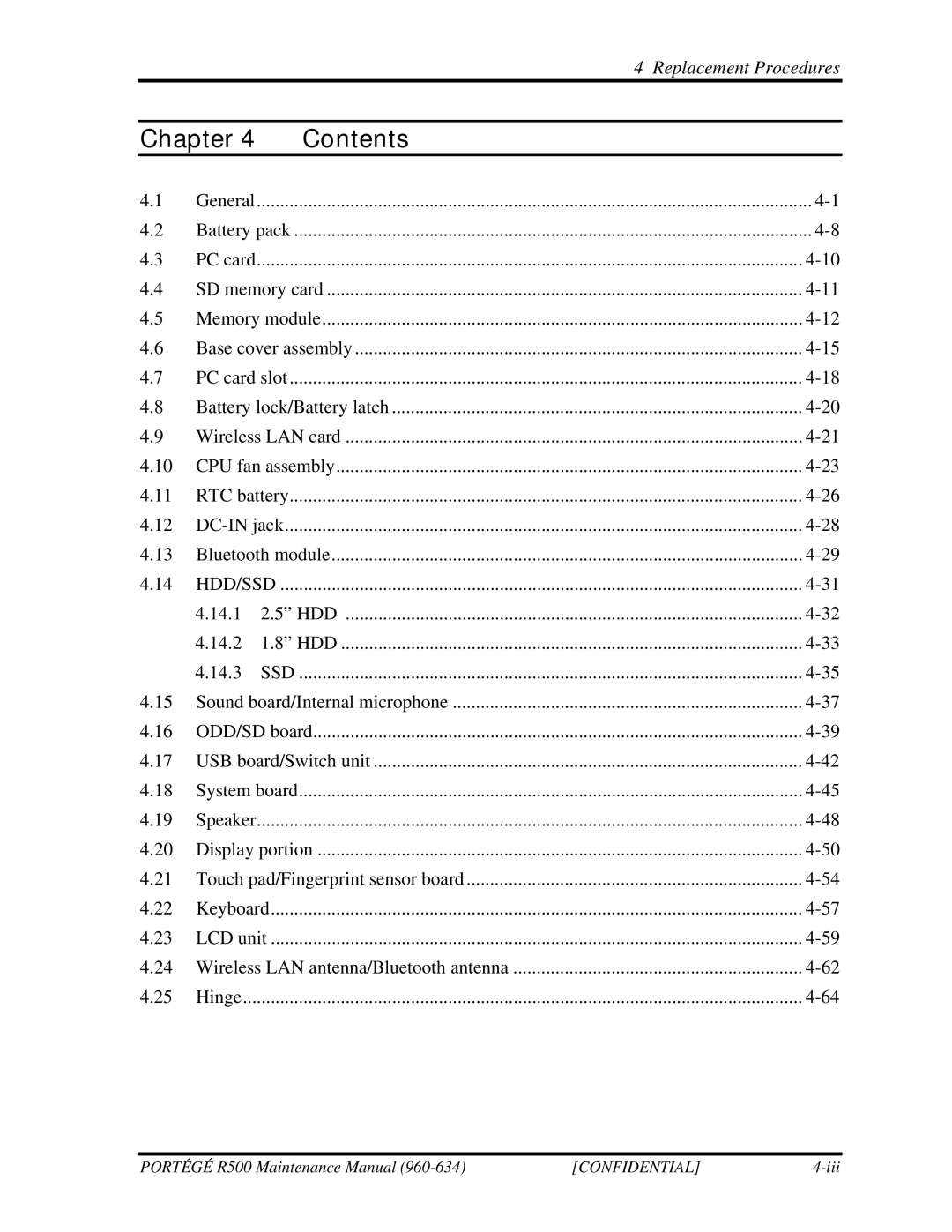
Chapter 4 | Contents |
| |
4.1 | General | ....................................................................................................................... | |
4.2 | Battery pack | ||
4.3 | PC card | ..................................................................................................................... | |
4.4 | SD memory card | ||
4.5 | Memory module | ||
4.6 | Base cover assembly | ||
4.7 | PC card slot | ||
4.8 | Battery lock/Battery latch | ||
4.9 | Wireless LAN card | ||
4.10 | CPU fan assembly | ||
4.11 | RTC battery | ||
4.12 | |||
4.13 | Bluetooth module | ||
4.14 | HDD/SSD | ||
| 4.14.1 | 2.5” HDD | |
| 4.14.2 | 1.8” HDD | |
| 4.14.3 | SSD | |
4.15 | Sound board/Internal microphone | ||
4.16 | ODD/SD board | ||
4.17 | USB board/Switch unit | ||
4.18 | System board | ||
4.19 | Speaker | ..................................................................................................................... | |
4.20 | Display portion | ||
4.21 | Touch pad/Fingerprint sensor board | ||
4.22 | Keyboard | ||
4.23 | LCD unit | ||
4.24 | Wireless LAN antenna/Bluetooth antenna | ||
4.25 | Hinge | ||
PORTÉGÉ R500 Maintenance Manual | [CONFIDENTIAL] |
