4.6 Base cover assembly | 4 Replacement Procedures |
4.6Base cover assembly
Removing the Base cover assembly
Click here to view caution on the disassembly/reassembly of the unit.
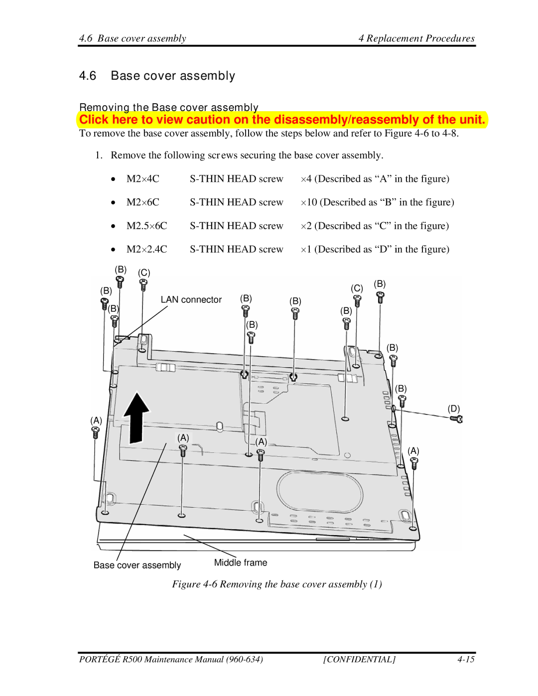
To remove the base cover assembly, follow the steps below and refer to Figure
1. Remove the following screws securing the base cover assembly.
• | M2×4C | ||
• | M2×6C | ||
• | M2.5×6C | ×2 (Described as “C” in the figure) | |
• | M2×2.4C | ×1 (Described as “D” in the figure) | |
(B)(C)
(B) |
| (C) | (B) |
(B) |
| ||
LAN connector | (B) |
| |
(B) |
| (B) |
|
| (B) |
|
|
(B)
(B)
(D)
(A)
(A)(A)
(A)
Base cover assembly | Middle frame |
Figure 4-6 Removing the base cover assembly (1)
PORTÉGÉ R500 Maintenance Manual | [CONFIDENTIAL] |