4 Replacement Procedures | 4.17 USB board/Switch unit |
4.17 USB board/Switch unit
Removing the USB board/Switch unit
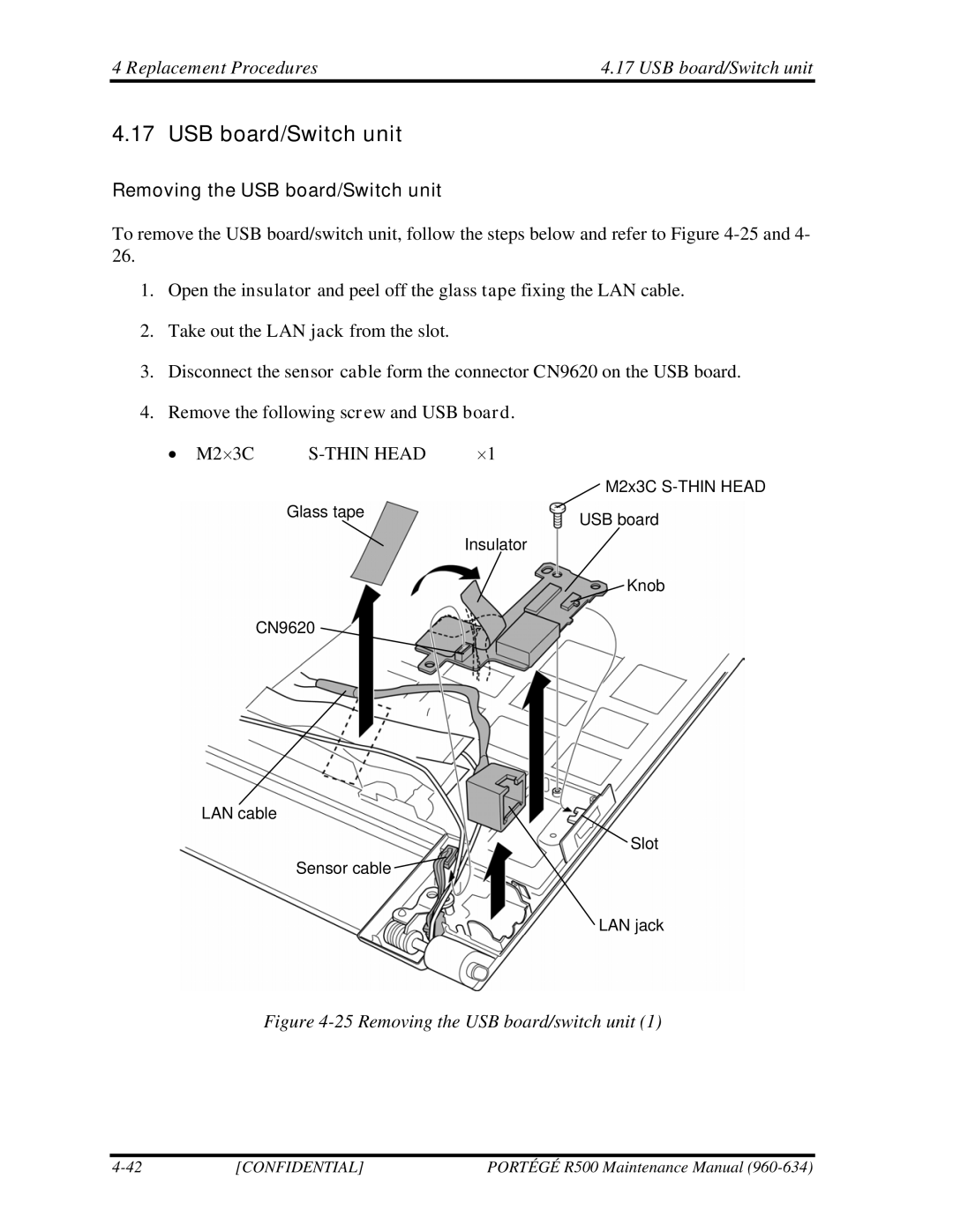
To remove the USB board/switch unit, follow the steps below and refer to Figure
1.Open the insulator and peel off the glass tape fixing the LAN cable.
2.Take out the LAN jack from the slot.
3.Disconnect the sensor cable form the connector CN9620 on the USB board.
4.Remove the following screw and USB board.
• M2×3C |
| ×1 |
|
| M2x3C |
| Glass tape | USB board |
|
| |
|
| Insulator |
|
| Knob |
| CN9620 |
|
LAN cable
![]() Slot
Slot
Sensor cable ![]()
LAN jack
Figure 4-25 Removing the USB board/switch unit (1)
[CONFIDENTIAL] | PORTÉGÉ R500 Maintenance Manual |
