4.16 ODD/SD board | 4 Replacement Procedures |
4.16 ODD/SD board
Removing the ODD/SD board
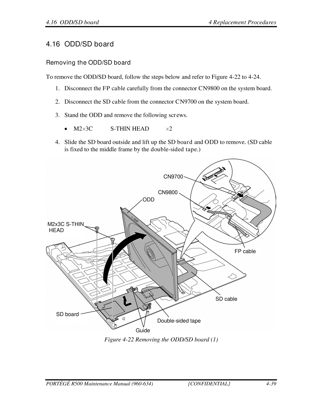
To remove the ODD/SD board, follow the steps below and refer to Figure
1.Disconnect the FP cable carefully from the connector CN9800 on the system board.
2.Disconnect the SD cable from the connector CN9700 on the system board.
3.Stand the ODD and remove the following screws.
• M2×3C |
| ×2 |
4.Slide the SD board outside and lift up the SD board and ODD to remove. (SD cable is fixed to the middle frame by the
CN9700
CN9800
ODD
M2x3C
HEAD
FP cable
SD cable
SD board ![]()
Guide
Figure 4-22 Removing the ODD/SD board (1)
PORTÉGÉ R500 Maintenance Manual | [CONFIDENTIAL] |
