VIVOTEK
Hierarchical Management Tree
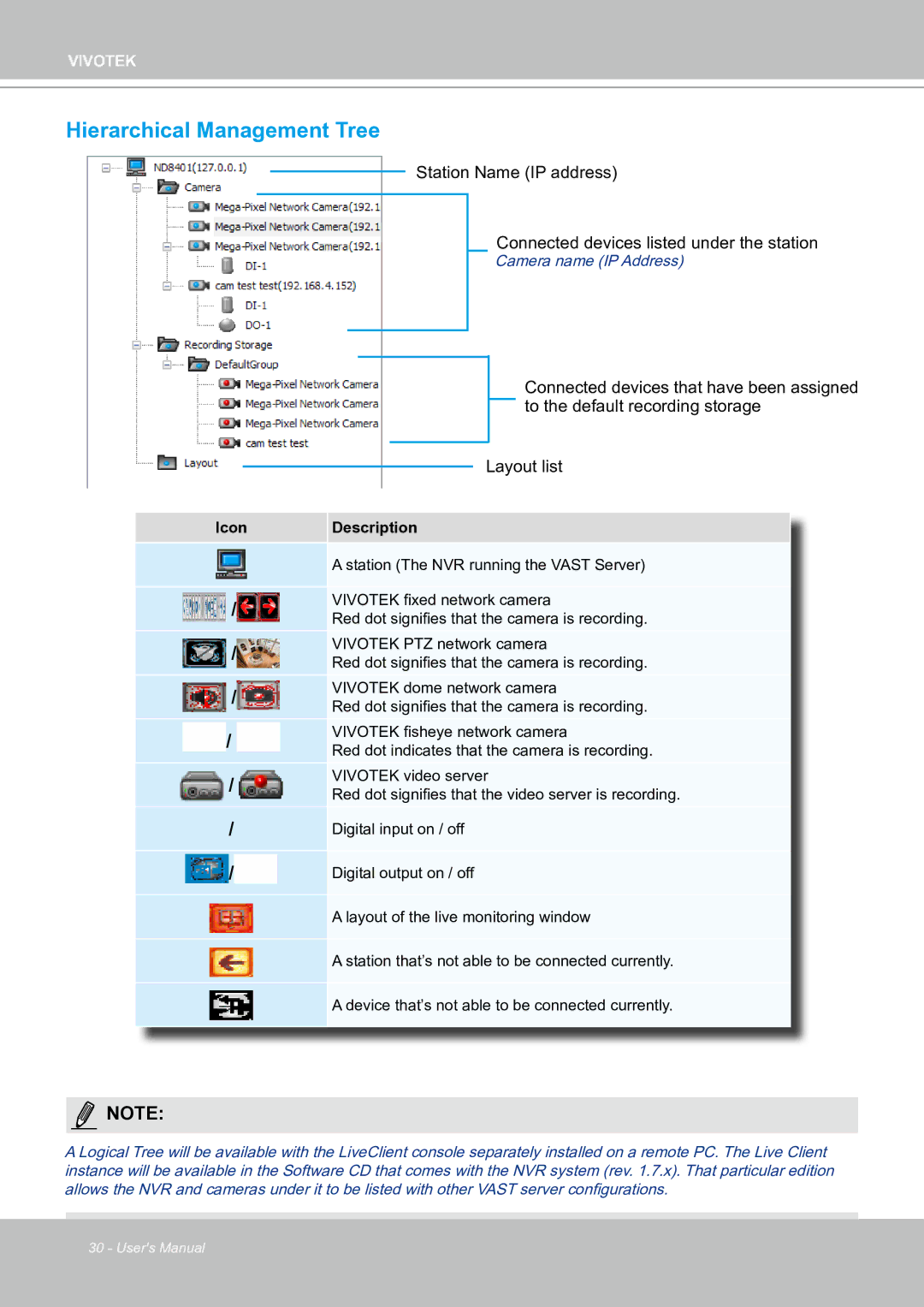
Station Name (IP address)
Connected devices listed under the station
Camera name (IP Address)
|
|
|
|
|
|
| Connected devices that have been assigned |
|
|
|
|
|
|
| to the default recording storage |
|
|
|
|
|
|
| |
|
|
|
|
|
|
|
|
|
|
|
|
| Layout list | ||
|
|
|
|
| |||
Icon | Description | ||||||
|
| A station (The NVR running the VAST Server) | |||||
/VIVOTEK fixed network camera
Red dot signifies that the camera is recording.
/VIVOTEK PTZ network camera
Red dot signifies that the camera is recording.
/VIVOTEK dome network camera
Red dot signifies that the camera is recording.
/VIVOTEK fisheye network camera
Red dot indicates that the camera is recording.
/VIVOTEK video server
Red dot signifies that the video server is recording.
/ | Digital input on / off |
/ | Digital output on / off |
A layout of the live monitoring window
A station that’s not able to be connected currently.
A device that’s not able to be connected currently.
NOTE:
A Logical Tree will be available with the LiveClient console separately installed on a remote PC. The Live Client instance will be available in the Software CD that comes with the NVR system (rev. 1.7.x). That particular edition allows the NVR and cameras under it to be listed with other VAST server configurations.
30 - User's Manual