Xerox 6030/6050/6050A
Page
Preface
Conventions
Safety Notes
Safety Notes
Iii
Maintenance
Operator Accessible Areas
Cleaning Your Product
Electrical Supply
Emergency Power Off
Disconnect Device
Operational Safety Information
Ozone Safety Information
Maintenance Information
State of Vermont Mercury Labeling Law
For Consumables
Canadian EME
Product Safety Certification
CE Mark
Regulatory Information
USA Energy Star 6030/6050 Wide Format
Environmental Compliance
USA Energy Star 6050A Wide Format
Canada Environmental Choice
Product Recycling and Disposal
Postal money Orders
Illegal Copies and Printouts
Illegal Copies and Printouts
Canada
Other Countries
Safety Extra Low Voltage Approval
Xviii
Table of Contents
Printer Setup
165
Chapter Additional Operations from the Printer Menu
Chapter Maintenance
Page
Chapter Product Overview
Xerox 6030/6050/6050A Wide Format Printer
Product Configurations
Xerox 6030/6050 Wide Format Copier/Printer
Xerox 6030/6050/6050A Wide Format Options
Xerox 6030/6050/6050A Wide Format Printer with Scan System
Major Components Front
Major Components
Major Components Rear
Page
Powering On 6050A
Power On/Off
Powering Off 6030/6050
Powering Off 6050A
Power Save Mode
Power Save Mode
OFF
Printer Control Panel Overview
Print Services on Web Overview 6050
Operating Modes
User Mode
Administrator Mode
How Logical Printers are Named T 0 0 H
Logical Printers Overview 6030/6050
Loading Roll Media
Procedure
Page
Setting Up Media
Standard size a
Drawer Media Size Indicators
Inch size a
Inserting media size sheets
Gently but firmly close the media tray
Loading Media for Manual Feeding
Make the required media settings on the copier control panel
Manual cut Open the media tray and slide the cutter manually
Cutting Roll Media
Cutting the Front Roll
Cutting Roll Media Manually
Window
Close the media tray
Cutting the Rear Roll
Page
Cutting Roll Media
Page
Chapter Printer Overview
Overview of the 6030/6050/6050A Wide Format Printer
What is the 6030/6050/6050A Wide Format Printer?
Data Formats that can be Processed 6030/6050
Communication Interfaces 6030/6050
Data Formats that can be Processed 6050A
Communication Interfaces 6050A
Printing Methods 6030/6050
Wide Format Windows Driver / PostScript Driver
Printing Methods 6050A
Printer Control Panel
Print Service Operations
Print Services on Web 6030/6050 only
Logical Printers 6030/6050 only
Main Printing Functions
Media Size Output
Document Size Input
Media Mapping/Automatic Mapping
Size Mapping
Mirror Image, 90-Degree Rotation
Plot Area, Auto-Layout, and Offset
Printing the Output Time
Split Drawing Image Fragmentation
Log Management
Reprinting
Job Recovery
Canceling Jobs
Meter Display
Printer Control Panel Usage
Button Functions
Basic Printer Control Panel Operations
Following buttons are used to navigate the menu screen
Previous Higher level Return to
Overview of the Operation Menu
Prints test patterns to help verify printer operation
Prints job and error logs
Reprints the most recently printed job
Operation Examples
Use the and keys to change the setting
Setting Up a Value
Smoothing
OFF
Timer Value
Low power mode1
Entering Numbers and Characters
Press the key Cursor will move to the second number
Operating Environment
Print Services on Web 6030/6050
Start Print Services on Web
Starting and Exiting Print Services on Web
Exit Print Services on Web
Administrator
Print Services on Web Organization
User
Printer Overview
Online Help
FreeFlow Accxes Web Print Management Tool 6050A
Users
System Administrators with the Password
Web Print Managment Tool Requirements
Web Printer Management Tool Security
Using Web Print Management Tool Main Menu
Chapter Printer Setup
Communication Parameters Definitions
Communication Parameters
Serial Centronics optional VPI optional
Snmp
Auto
Hpgl
Routing Table
Menu Item Description
Select ADD to enter additional routing
Dhcp
RARP/BOOTP Unix
XON/XOFF
Serial 6030/6050 Only
ENQ-ACK
Software
YES
Centronics optional, 6030/6050 Only
Report
VPI optional, 6030/6050 Only
Offline
Snmp 6030/6050 Only
TCP/IP Setup
Procedure
Menu Port Setting Port Setting TCP/IP
Hpgl
Routing Table ADD
Serial Setup
VPI optional Setup
Centronics optional Setup
Port Setting Centro
DMA Timeout 005 sec
YES
Menu System Settings
Communication Parameter Setup Printer Control Panel, 6050A
System Settings TCP/IP
Procedure
Printer Setup
Page
Printer Setup
Auto Roll
System Parameter Setup Printer Control Panel, 6030/6050
SPA Paper Width
Queued
6030/6050 Printer Control Panel Example Procedure
ALL
OFF
RARP/BOOTP to be enabled or disabled
System Settings Setup Printer Control Panel, 6050A
Allows the entering of an IP Address, IP Subnet Mask
An IP Gateway address. Also allows Dhcp
Menu System Settings System Settings TCP/IP Dhcp
6050A Printer Control Panel Example Procedure
Qinfopen
System Parameter Setup Print Services on Web, 6030/6050
Net Cont. Time
Exclusive access Time out Not available
Setting Up Priority
Setting Up Print Density
Setting Up Replot
Setting Up Paper Width for Special a
Setting Up Extension
Setting Up Job Recovery
Add an extension
Setting up Set date
Enter the date
System Parameter Setup Web Printer Management Tool, 6050A
From Print Services on Web
Printing a Configuration List 6050
Menu Port Setting Print Config
From the Printer Control Panel
Printer Setup
Printing a Configuration List 6030/6050
Description of the Configuration List Contents
Menu Utilities Test Print Printer Configuration
Printing a Configuration List 6050A
From Web Printer Management Tool
Printer Setup
Printing a Configuration List 6050A
100
Contents of the configuration list are explained below
101
Software Option Print Services on Web, 6030/6050
102
Software Option Web Printer Management Tool, 6050A
103
Change Password Print Services on Web, 6030/6050
104
Change Password Web Printer Management Tool, 6050A
105
Change Default Language Print Services on Web, 6030/6050
106
Change Default Language Web Printer Management Tool, 6050A
Chapter
108
Creating a New Logical Printer
109
110
111
Defining the Print Settings
112
Logical Printer Print Settings
Logical Printer Parameters by Data Format
Parameters Common to all Data Formats
113
Print Setup Menu Item Description Format
Parameters Unique to Data Formats
114
Tiff
Media Series
Settings
115
Arch series, ISO B series, Ansi series, and ARCH-30
Media Series ISO a ISO B
116
Arch Ansi ARCH-30
Media
117
Size/Media Mapping
Media Mapping
118
Example
119
Input size Output size Media size
120
Media Source
Manual
JOB
121
Media Type
122
User-Defined Size
123
Input Option
124
125
Input Size Margin
Media Margin
126
127
Plot Area
Disable
Enable
128
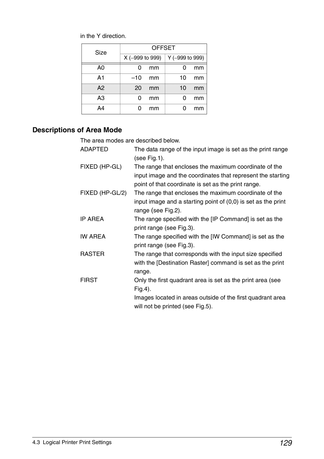
Offset
129
Descriptions of Area Mode
Adapted
First
131
132
Priority
133
Title Block
134
Split Drawing
135
136
Message Option
137
Copy count command in the job data
Sets up the default number of copies to be printed
Printed Copy
138
139
Output Option
Other
140
MIX
Long
Connect Margin
141
142
Size Recognition
Outputs images that are within the A0
143
Size, but exceed the standard size, on
One size larger standard shape paper
144
Color Option
145
Transform
Mirror Image
146
147
Define Single Pen
End style
148
Joint style
149
Unjoint
150
Bevel
Miter
151
Define Multi Pen
152
Pen Option
Pen width remains unchanged
153
Emulation
Selects the processing language for the HP-GL format only
Enables or disables the PS command
PS Command
154
Enables and disables the EOP command for HP-GL data only
EOP Command
155
Vcgl Pen Style Vcgl Define Pen
Sets up the pen specifications for Vcgl data only
156
Dashstyle
No Wrap
157
Wrap
158
Vcgl Pen Width
159
VRF Define Pen Define Single Pen
160
161
VRF Define Multi Pen
162
Tiff Option
163
Cals Option
Menu Item Specify Output Direction Description
164
165
Logical Printer Operations
166
Selecting the Media Type
167
Using Media Other Than the Default Series
168
Changing Output Roll Media for an Entire Job
Image Size Media Size
169
Reduction and Enlargement Using Size Mapping
Input Size Output Size
170
Printing Long Documents
Display the Print Queue
Print Services on Web Job and Log
171
Items Displayed in the Jobs not completed List
172
173
174
Cancel and Change the Priority of Jobs
175
176
Manage the Job and Error Logs
Job Log
Display the Job Log
Print the Job Log manually
177
178
Print the Job Log automatically
179
180
Delete the Job Log
181
182
Save the Job Log
183
184
185
Display the Error Log
186
Saving, Deleting, Printing the Error Log
Display Printer Status
Print Services on Web Status
187
Items Displayed on the Status tab
188
IOT Status Details
189
190
Print a Test Pattern
Print Services on Web Tools
191
192
Print a Diagnostic Report
193
Manual Feed Printing
194
Chapter Additional Operations from the Printer Menu
196
Introduction
197
Printer Control Panel Menu 6030/6050
Network Port/Set Menu
198
199
200
201
202
Print Setup Menu
203
Printer Control Panel Menu 6050A
Localization Menu
204
System Settings Menu
Utilities Menu
205
206
207
Test Printing 6030/6050 only
Menu Test Plot
Plot Size
Menu JOB Logging JOB LOG Setting
Managing the Job and Error Logs 6030/6050 only
Job Log
208
209
Auto Mode Print LOG 020423
Print
SET to Print
Menu JOB Logging JOB Logging Error LOG Error LOG Print
Error Log 6030/6050 only
210
Print LOG 020423 Press the key with JOB Logging displayed
211
Sample Error Log List
212
Reprinting 6030/6050 only
Menu Offline Plot Replot
Printed Copies
213
Billing Meter Confirmation 6030/6050
Meter
Menu Billing Info View Meter
214
Billing Meter Confirmation 6050A
Menu Utilities
Billing Meters
Setting Up Media
Print Setup Menu
215
Tray
216
217
Menu Print Setup
36, 24, 18, 12
Selecting Values
218
Media / Roll1 Type Bond
219
Media / Roll1 Type Film
Media Roll1 Type Film
220
Automatic Cut Using the Printer Control Panel
221
Fuser
Tray
222
Chapter Ethernet Print Service For Unix
224
Overview of the Ethernet Print Service
Host System Registration
Registering the Xerox 6030/6050 Wide Format Printer System
225
SunOS
226
Registering the Remote Printer
227
Setting the MAC frame format
AIX
228
Registering the Xerox 6050A Wide Format Printer System
229
230
Details of the ftp command are explained below
Printing Using the ftp Command Only
Printing
231
232
Specify the bin subcommand for a data format
233
This section explains the ftp subcommands
Other Subcommands
234
235
Message List
236
237
238
239
Printing lpr Command
Printing Using the lp/lpr Command
Details of each command are explained
240
Usage Examples 6030/6050
241
Usage Examples 6050A
242
243
Printing lp Command for SunOS
Examples of use
244
Status Display lpq Command
245
246
Cancel lprm Command
247
248
249
Message List 6030/6050 only
250
Chapter Maintenance
252
Loading Toner
253
254
Chapter Problem Solving
256
Check the Control Panels
257
Poor Image Quality
258
Other Problems
259
Printer Troubleshooting
260
Disable
261
Jams in the Feeder Roll Media
Rotate the roll until the lead edge is gripped Roller
Window
262
263
Jams in the Printer and Ejection Port
Pull the jammed media slowly toward you to remove it
264
Chapter Specifications
266
Main Specifications 6030/6050
Supported data formats
Relationship between data formats and interfaces
Host system interfaces
267
Ethernet connection
Physical interface 100Base-TX and 10Base-T
Standard sizes and drawing areas
268
SP. a
269
Print Length
270
271
Configuration
Frame memory Maximum number of spools
Mounted Number of sheets
272
Main Specifications 6050A
273
960 ⋅ 7,008 26 x SP. A0
274
215.9 x 279.4 mm
275
Paper Type Paper Width 512MB Standard
276
Maximum print length = 50,000mm
277
Media Specifications
Tracing Paper 24 to 29lb to 112 gsm
Main Specifications
Machine Specifications 6030/6050
278
OPC
Scsi ID
279
280
281
Machine Specifications 6050A
282
Appendixes
RS-232C pin assignment 6030/6050 only
Appendix 1 Connector Specifications
Centronics pin assignment
GND
Data STB Fault GND ACK Busy Select
Command List
Appendix 2 HP-GL/HP-GL2 Command List 6030/6050
Command not supported and ignored
Command Meaning and action
Appendix 2 HP-GL/HP-GL2 Command List 6030/6050
HP-GL HP-GL/2
HP-GL HP-GL/2
HP-GL HP-GL/2
HP-GL HP-GL/2
Appendix 3 HP-RTL Command List 6050
Sets the controller to the raster mode
Saves and restores palette Ignored Information
Specified value in Versatec resolution Inch units
Assigns a defined RGB parameter to Index Number
Defines the input image resolution
Succeeding Start Graphic command By decipoint 1/720 inch
Defines the raster output width for
Defines the raster output height for
Ccitt T6 MMR
Appendix 4 Tiff Tag List 6030/6050
Cmyk
Mgbæ LSB Lsbæ MGB
Tag ID Revision 6030/6050 Tag Name
Tag ID Revision 6030/6050 Tag Name
8298 33432 Copyright
Hex
Appendixes
Symbols
Interface33, 267
Pen attributes147, 151, 159
VPI67