Technical Data
16.Assure that the Flow Switch is properly in- stalled, wired correctly, and working.
17.Assure bolts through compressor feet to bottom frame rails are removed.
PANEL CHECKS
(Power ON – Both System Switches “OFF”)
1.Apply
2.Apply 115VAC and verify its value on the ter- minal block in the lower left of the Power Panel. Make the measurement between terminals 5 and 2 (See Fig. 14, page 41). The voltage should be 115VAC +/- 10%.
3.Assure the heaters on each compressor are on. Allow the compressor heaters to remain on a minimum of 24 hours before
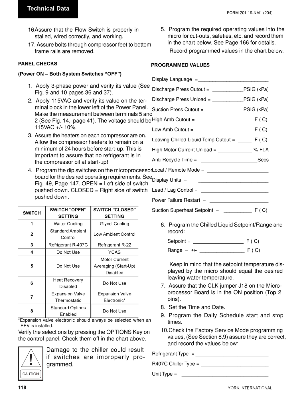
4.Program the dip switches on the microprocessor board for the desired operating requirements. See Fig. 49, Page 147. OPEN = Left side of switch pushed down. CLOSED = Right side of switch pushed down.
SWITCH | SWITCH "OPEN" | SWITCH "CLOSED" | |
SETTING | SETTING | ||
| |||
1 | Water Cooling | Glycol Cooling | |
2 | Standard Ambient | Low Ambient Control | |
Control | |||
|
| ||
3 | Refrigerant | Refrigerant | |
4 | Do Not Use | YCAS | |
|
| Motor Current | |
5 | Do Not Use | Averaging | |
|
| Disabled | |
6 | Heat Recovery | Do Not Use | |
Disabled | |||
|
| ||
7 | Expansion Valve | Expansion Valve | |
Thermostatic | Electronic* | ||
| |||
8 | Standard Options | Do Not Use | |
Enabled | |||
|
|
*Expansion valve electronic should always be selected when an EEV is installed.
Verify the selections by pressing the OPTIONS Key on the control panel. Check them off in the chart above.
Damage to the chiller could result if switches are improperly pro- grammed.
FORM
5.Program the required operating values into the micro for
Record programmed values in the chart below.
PROGRAMMED VALUES
Display Language = _________________________
Discharge Press Cutout = ___________PSIG (kPa)
Discharge Press Unload = ___________PSIG (kPa)
Suction Press Cutout = _____________PSIG (kPa)
High Amb Cutout = ___________________ °F (°C)
Low Amb Cutout = ____________________ °F (°C)
Leaving Chilled Liquid Temp Cutout = _____ °F (°C)
High Motor Current Unload = ____________ % FLA
Local / Remote Mode = ______________________
Display Units = _________________________
Lead / Lag Control = ________________________
Power Failure Restart = _____________________
Suction Superheat Setpoint = __________ °F (°C)
6.Program the Chilled Liquid Setpoint/Range and record:
Setpoint = __________________ °F (°C) Range = +/- ________________ °F (°C)
Keep in mind that the setpoint temperature dis- played by the micro should equal the desired leaving water temperature.
7.Assure that the CLK jumper J18 on the Micro- processor Board is in the ON position (Top 2 pins).
8.Set the Time and Date.
9.Program the Daily Schedule start and stop times.
10.Check the Factory Service Mode programming values, (See Section 8.9) assure they are correct, and record the values below:
Refrigerant Type = __________________________
R407C Chiller Type = ________________________
Unit Type = _______________________________
118 | YORK INTERNATIONAL |
