Product Description
Motor Protection Modules (2ACE)
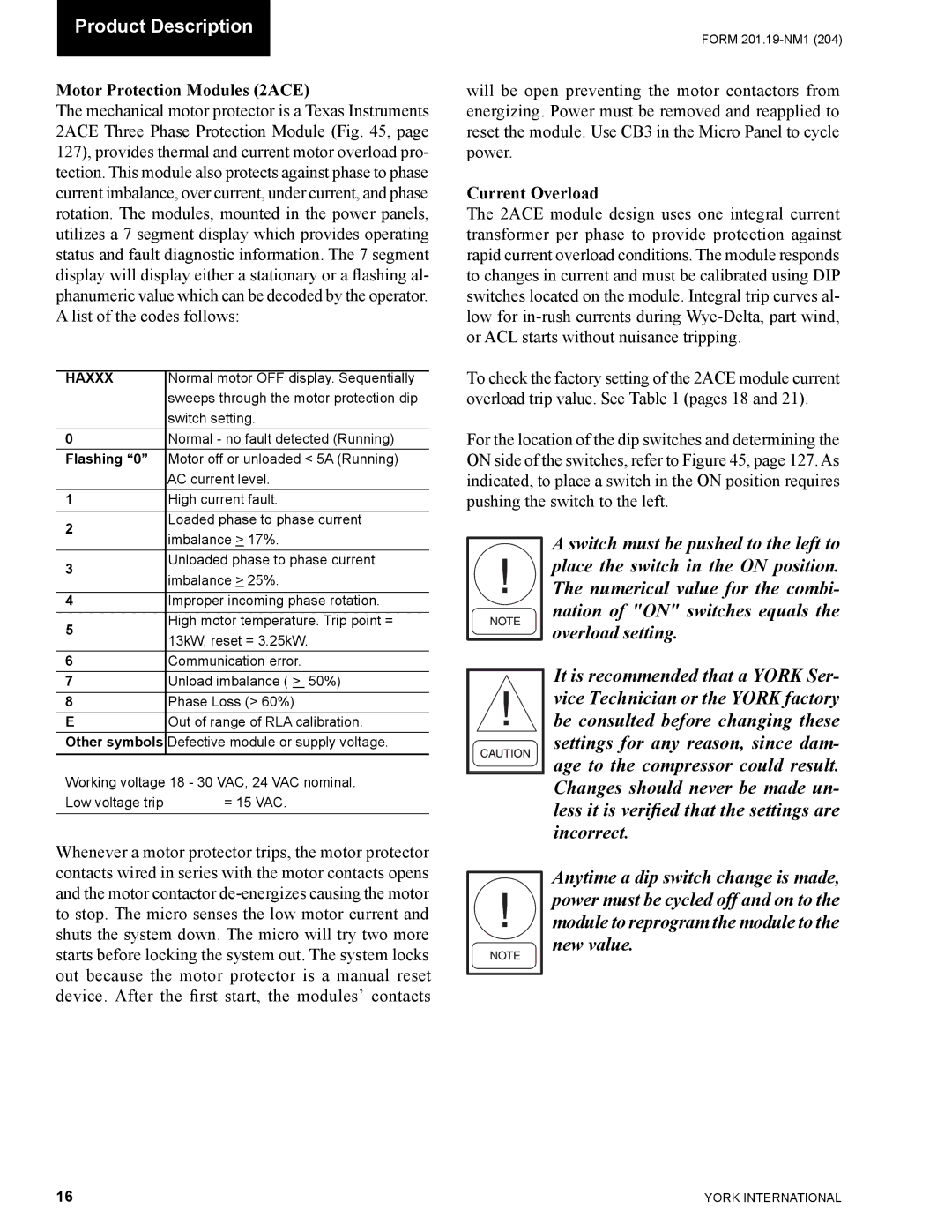
The mechanical motor protector is a Texas Instruments 2ACE Three Phase Protection Module (Fig. 45, page 127), provides thermal and current motor overload pro- tection. This module also protects against phase to phase current imbalance, over current, under current, and phase rotation. The modules, mounted in the power panels, utilizes a 7 segment display which provides operating status and fault diagnostic information. The 7 segment display will display either a stationary or a flashing al- phanumeric value which can be decoded by the operator. A list of the codes follows:
HAXXX | Normal motor OFF display. Sequentially | |
| sweeps through the motor protection dip | |
| switch setting. | |
0 | Normal - no fault detected (Running) | |
Flashing “0” | Motor off or unloaded < 5A (Running) | |
| AC current level. | |
1 | High current fault. | |
2 | Loaded phase to phase current | |
imbalance > 17%. | ||
| ||
3 | Unloaded phase to phase current | |
imbalance > 25%. | ||
| ||
|
| |
4 | Improper incoming phase rotation. | |
5 | High motor temperature. Trip point = | |
13kW, reset = 3.25kW. | ||
| ||
6 | Communication error. | |
7 | Unload imbalance ( > 50%) | |
8 | Phase Loss (> 60%) | |
E | Out of range of RLA calibration. | |
Other symbols | Defective module or supply voltage. |
Working voltage 18 - 30 VAC, 24 VAC nominal.
Low voltage trip | = 15 VAC. |
Whenever a motor protector trips, the motor protector contacts wired in series with the motor contacts opens and the motor contactor
FORM
will be open preventing the motor contactors from energizing. Power must be removed and reapplied to reset the module. Use CB3 in the Micro Panel to cycle power.
Current Overload
The 2ACE module design uses one integral current transformer per phase to provide protection against rapid current overload conditions. The module responds to changes in current and must be calibrated using DIP switches located on the module. Integral trip curves al- low for
To check the factory setting of the 2ACE module current overload trip value. See Table 1 (pages 18 and 21).
For the location of the dip switches and determining the ON side of the switches, refer to Figure 45, page 127. As indicated, to place a switch in the ON position requires pushing the switch to the left.
A switch must be pushed to the left to place the switch in the ON position. The numerical value for the combi- nation of "ON" switches equals the overload setting.
It is recommended that a YORK Ser- vice Technician or the YORK factory be consulted before changing these settings for any reason, since dam- age to the compressor could result. Changes should never be made un- less it is verified that the settings are incorrect.
Anytime a dip switch change is made, power must be cycled off and on to the module to reprogram the module to the new value.
16 | YORK INTERNATIONAL |
