FORM
8.12 ISN CONTROL
RECEIVED DATA (CONTROL DATA) | TRANSMITTED DATA |
8
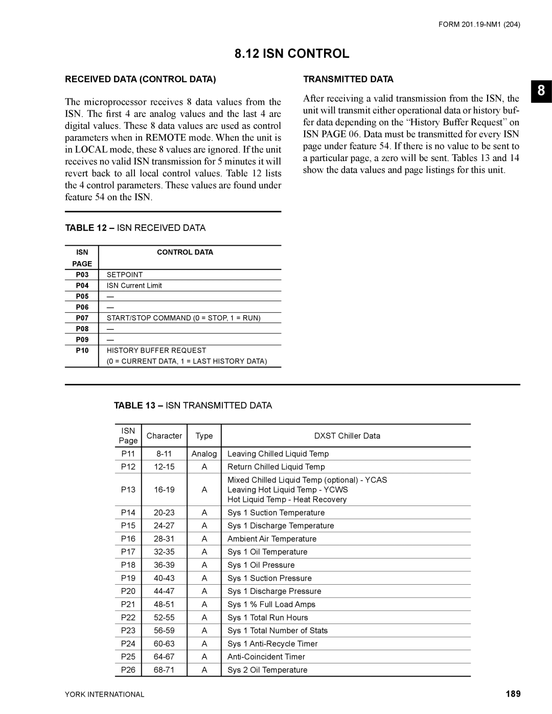
The microprocessor receives 8 data values from the ISN. The first 4 are analog values and the last 4 are digital values. These 8 data values are used as control parameters when in REMOTE mode. When the unit is in LOCAL mode, these 8 values are ignored. If the unit receives no valid ISN transmission for 5 minutes it will revert back to all local control values. Table 12 lists the 4 control parameters. These values are found under feature 54 on the ISN.
TABLE 12 – ISN RECEIVED DATA
ISN | CONTROL DATA |
PAGE |
|
P03 | SETPOINT |
P04 | ISN Current Limit |
P05 | — |
P06 | — |
P07 | START/STOP COMMAND (0 = STOP, 1 = RUN) |
P08 | — |
P09 | — |
P10 | HISTORY BUFFER REQUEST |
| (0 = CURRENT DATA, 1 = LAST HISTORY DATA) |
After receiving a valid transmission from the ISN, the unit will transmit either operational data or history buf- fer data depending on the “History Buffer Request” on ISN PAGE 06. Data must be transmitted for every ISN page under feature 54. If there is no value to be sent to a particular page, a zero will be sent. Tables 13 and 14 show the data values and page listings for this unit.
TABLE 13 – ISN TRANSMITTED DATA
ISN | Character | Type | DXST Chiller Data | |
Page | ||||
|
|
| ||
P11 | Analog | Leaving Chilled Liquid Temp | ||
P12 | A | Return Chilled Liquid Temp | ||
|
|
| Mixed Chilled Liquid Temp (optional) - YCAS | |
P13 | A | Leaving Hot Liquid Temp - YCWS | ||
|
|
| Hot Liquid Temp - Heat Recovery | |
P14 | A | Sys 1 Suction Temperature | ||
P15 | A | Sys 1 Discharge Temperature | ||
P16 | A | Ambient Air Temperature | ||
P17 | A | Sys 1 Oil Temperature | ||
P18 | A | Sys 1 Oil Pressure | ||
P19 | A | Sys 1 Suction Pressure | ||
P20 | A | Sys 1 Discharge Pressure | ||
P21 | A | Sys 1 % Full Load Amps | ||
P22 | A | Sys 1 Total Run Hours | ||
P23 | A | Sys 1 Total Number of Stats | ||
P24 | A | Sys 1 | ||
P25 | A | |||
P26 | A | Sys 2 Oil Temperature |
YORK INTERNATIONAL | 189 |