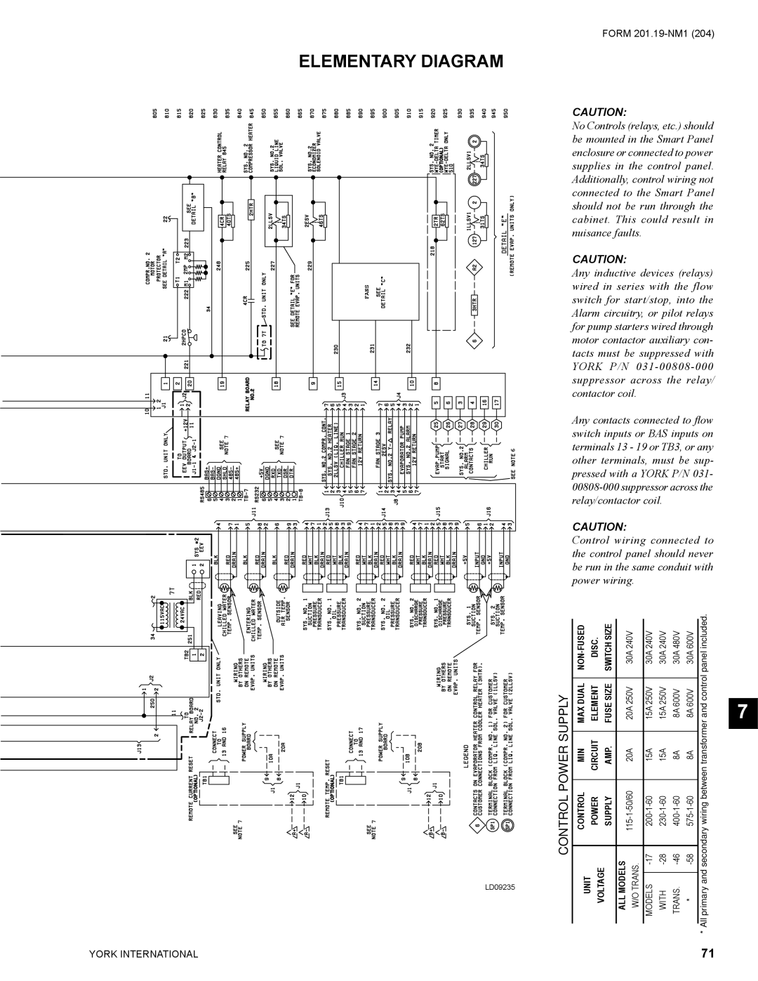
ELEMENTARY DIAGRAM
FANS
7 | 7 |
6
7 | 7 |
LD09235
FORM
CAUTION:
No Controls (relays, etc.) should be mounted in the Smart Panel enclosure or connected to power supplies in the control panel. Additionally, control wiring not connected to the Smart Panel should not be run through the cabinet. This could result in nuisance faults.
CAUTION:
Any inductive devices (relays) wired in series with the flow switch for start/stop, into the Alarm circuitry, or pilot relays for pump starters wired through motor contactor auxiliary con- tacts must be suppressed with YORK P/N
Any contacts connected to flow switch inputs or BAS inputs on terminals 13 - 19 or TB3, or any other terminals, must be sup- pressed with a YORK P/N 031-
CAUTION:
Control wiring connected to the control panel should never be run in the same conduit with power wiring.
| DISC. | SWITCH SIZE |
| 30A 240V |
| 30A 240V | 30A 240V | 30A 480V | 30A 600V |
| panel included. | ||
|
|
|
| ||||||||||
CONTROLPOWER SUPPLY |
|
|
|
|
|
|
|
|
| betweenwiringsecondaryandprimary transformer and control | |||
UNIT VOLTAGE |
| MODELSALL TRANS.W/O |
|
| |||||||||
| DUALMAX | ELEMENT | SIZEFUSE |
| 250V20A |
|
|
|
|
|
|
| 7 |
| MIN | CIRCUIT | AMP. |
| 20A |
|
|
|
|
|
|
|
|
| CONTROL | POWER | SUPPLY |
|
|
|
|
|
|
|
|
| |
|
|
|
|
|
|
|
|
|
|
|
| * All | |
|
|
|
|
|
|
|
|
|
|
|
| ||
|
|
|
|
|
|
|
|
|
|
|
| ||
|
|
|
|
|
|
|
|
|
|
|
| ||
YORK INTERNATIONAL | 71 |