PIPEWORK ARRANGEMENT
Figure #6 shows the suggested pipework arrangement for single unit installations. For multiple unit installa- tions, each unit should be piped as shown.
CONNECTION TYPES & SIZES
For connection sizes relevant to individual models refer to the Technical Data Section.
EVAPORATOR CONNECTIONS
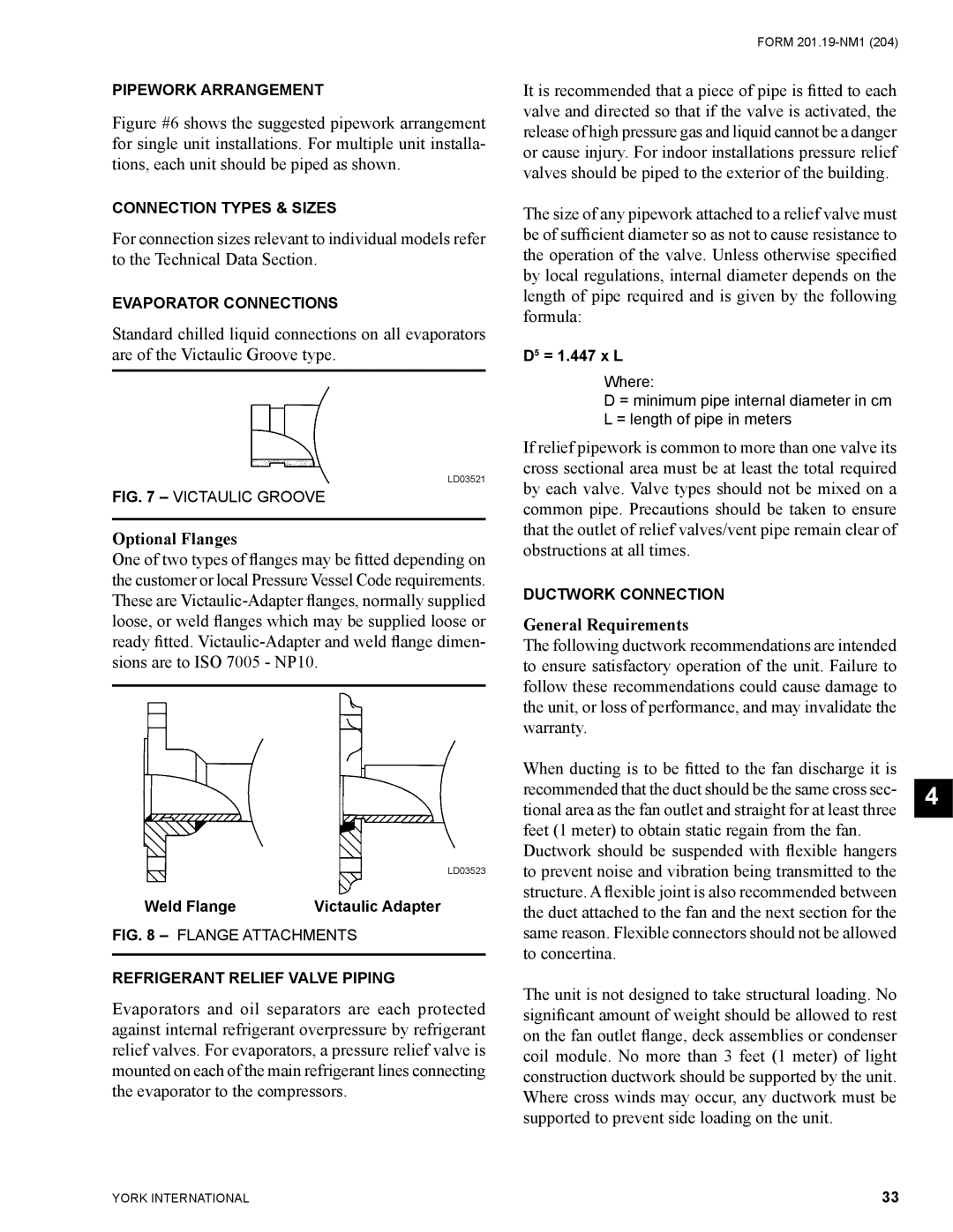
Standard chilled liquid connections on all evaporators are of the Victaulic Groove type.
LD03521
FIG. 7 – VICTAULIC GROOVE
Optional Flanges
One of two types of flanges may be fitted depending on the customer or local Pressure Vessel Code requirements. These are
LD03523
Weld Flange | Victaulic Adapter |
FIG. 8 – FLANGE ATTACHMENTS
REFRIGERANT RELIEF VALVE PIPING
Evaporators and oil separators are each protected against internal refrigerant overpressure by refrigerant relief valves. For evaporators, a pressure relief valve is mounted on each of the main refrigerant lines connecting the evaporator to the compressors.
FORM
It is recommended that a piece of pipe is fitted to each valve and directed so that if the valve is activated, the release of high pressure gas and liquid cannot be a danger or cause injury. For indoor installations pressure relief valves should be piped to the exterior of the building.
The size of any pipework attached to a relief valve must be of sufficient diameter so as not to cause resistance to the operation of the valve. Unless otherwise specified by local regulations, internal diameter depends on the length of pipe required and is given by the following formula:
D5 = 1.447 x L
Where:
D = minimum pipe internal diameter in cm L = length of pipe in meters
If relief pipework is common to more than one valve its cross sectional area must be at least the total required by each valve. Valve types should not be mixed on a common pipe. Precautions should be taken to ensure that the outlet of relief valves/vent pipe remain clear of obstructions at all times.
DUCTWORK CONNECTION
General Requirements
The following ductwork recommendations are intended to ensure satisfactory operation of the unit. Failure to follow these recommendations could cause damage to the unit, or loss of performance, and may invalidate the warranty.
When ducting is to be fitted to the fan discharge it is recommended that the duct should be the same cross sec- tional area as the fan outlet and straight for at least three feet (1 meter) to obtain static regain from the fan.
Ductwork should be suspended with flexible hangers to prevent noise and vibration being transmitted to the structure. A flexible joint is also recommended between the duct attached to the fan and the next section for the same reason. Flexible connectors should not be allowed to concertina.
The unit is not designed to take structural loading. No significant amount of weight should be allowed to rest on the fan outlet flange, deck assemblies or condenser coil module. No more than 3 feet (1 meter) of light construction ductwork should be supported by the unit. Where cross winds may occur, any ductwork must be supported to prevent side loading on the unit.
4
YORK INTERNATIONAL | 33 |