Refrigerant gas is drawn into the void created by the unmeshing of the five lobed male and seven lobed female rotor. Further meshing of the rotors closes the rotor threads to the suction port and progressively compresses the gas in an axial direction to the discharge port. The gas is compressed in volume and increased in pressure before exiting at a designed volume at the discharge end of the rotor casing. Since the intake and discharge cycles overlap, a resulting smooth flow of gas is maintained.
The rotors are housed in a cast iron compressor housing precision machined to provide optimal clearances for the rotors. Contact between the male and female rotor is primarily rolling on a contact band on each of the rotor’s pitch circle. This results in virtually no rotor wear and increased reliability, a trademark of the screw compressor.
The compressor incorporates a complete
Motor cooling is provided by suction gas from the evaporator flowing across the motor. Redundant overload protection is provided using both thermistor and current overload protection.
00485VIP
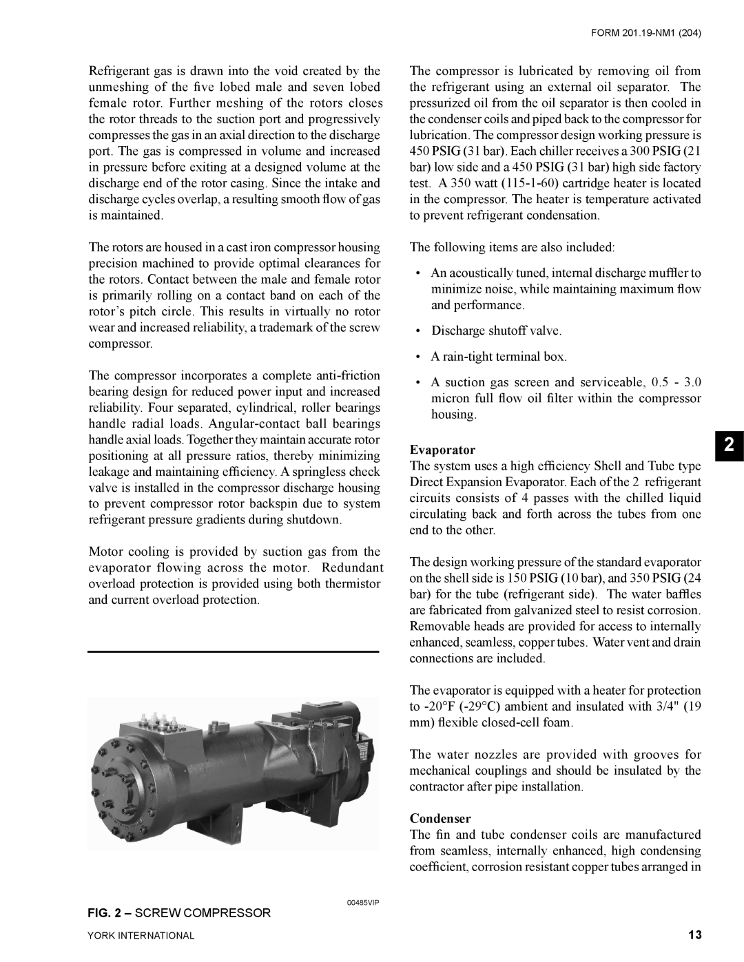
FIG. 2 – SCREW COMPRESSOR
FORM
The compressor is lubricated by removing oil from the refrigerant using an external oil separator. The pressurized oil from the oil separator is then cooled in the condenser coils and piped back to the compressor for lubrication. The compressor design working pressure is 450 PSIG (31 bar). Each chiller receives a 300 PSIG (21 bar) low side and a 450 PSIG (31 bar) high side factory test. A 350 watt
The following items are also included:
•An acoustically tuned, internal discharge muffler to minimize noise, while maintaining maximum flow and performance.
•Discharge shutoff valve.
•A
•A suction gas screen and serviceable, 0.5 - 3.0 micron full flow oil filter within the compressor housing.
Evaporator
The system uses a high efficiency Shell and Tube type Direct Expansion Evaporator. Each of the 2 refrigerant circuits consists of 4 passes with the chilled liquid circulating back and forth across the tubes from one end to the other.
The design working pressure of the standard evaporator on the shell side is 150 PSIG (10 bar), and 350 PSIG (24 bar) for the tube (refrigerant side). The water baffles are fabricated from galvanized steel to resist corrosion. Removable heads are provided for access to internally enhanced, seamless, copper tubes. Water vent and drain connections are included.
The evaporator is equipped with a heater for protection to
The water nozzles are provided with grooves for mechanical couplings and should be insulated by the contractor after pipe installation.
Condenser
The fin and tube condenser coils are manufactured from seamless, internally enhanced, high condensing coefficient, corrosion resistant copper tubes arranged in
2
YORK INTERNATIONAL | 13 |