Installation
Where accumulation of snow is likely, additional height must be provided under the unit to ensure normal airflow to the unit.
The clearance dimensions given are necessary to maintain good airflow and ensure correct unit operation. It is also necessary to consider access requirements for safe operation and maintenance of the unit and power and control panels. Local health and safety regulations, or practical con- siderations for service replacement of large components, may require larger clearances than those given in the Technical Data Section of this manual, (page 90).
FORM
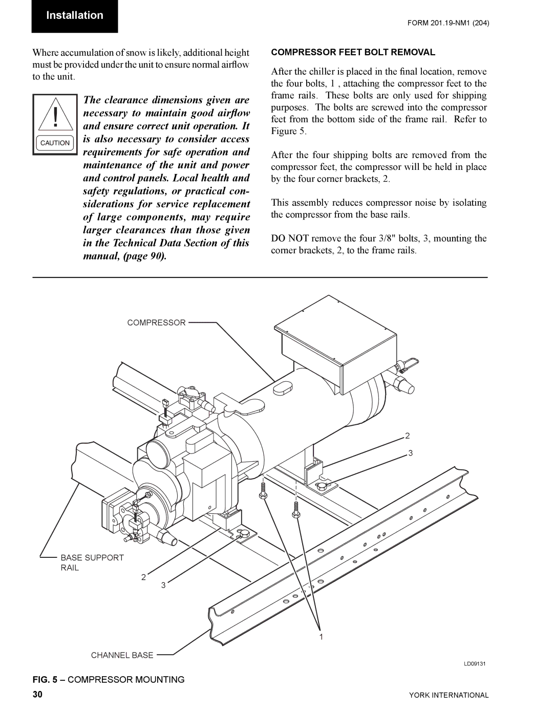
COMPRESSOR FEET BOLT REMOVAL
After the chiller is placed in the final location, remove the four bolts, 1 , attaching the compressor feet to the frame rails. These bolts are only used for shipping purposes. The bolts are screwed into the compressor feet from the bottom side of the frame rail. Refer to Figure 5.
After the four shipping bolts are removed from the compressor feet, the compressor will be held in place by the four corner brackets, 2.
This assembly reduces compressor noise by isolating the compressor from the base rails.
DO NOT remove the four 3/8" bolts, 3, mounting the corner brackets, 2, to the frame rails.
COMPRESSOR
2
3
BASE SUPPORT RAIL
2
3
1
CHANNEL BASE
LD09131
FIG. 5 – COMPRESSOR MOUNTING
30 | YORK INTERNATIONAL |