Manuals
/
York
/
Household Appliance
/
Fan
York
YCAS0130
manual
#3/#4 #5/#6 #7/#8 #9/#10
Models:
YCAS0130
1
80
204
204
Download
204 pages
14.22 Kb
77
78
79
80
81
82
83
84
Troubleshooting
Install
Wiring Diagram
Alarm Contacts
Anti-Recycle Timers
Safety Symbols
Dimension
Maintenance
Problem Possible Cause
Remote Current Reset
Page 80
Image 80
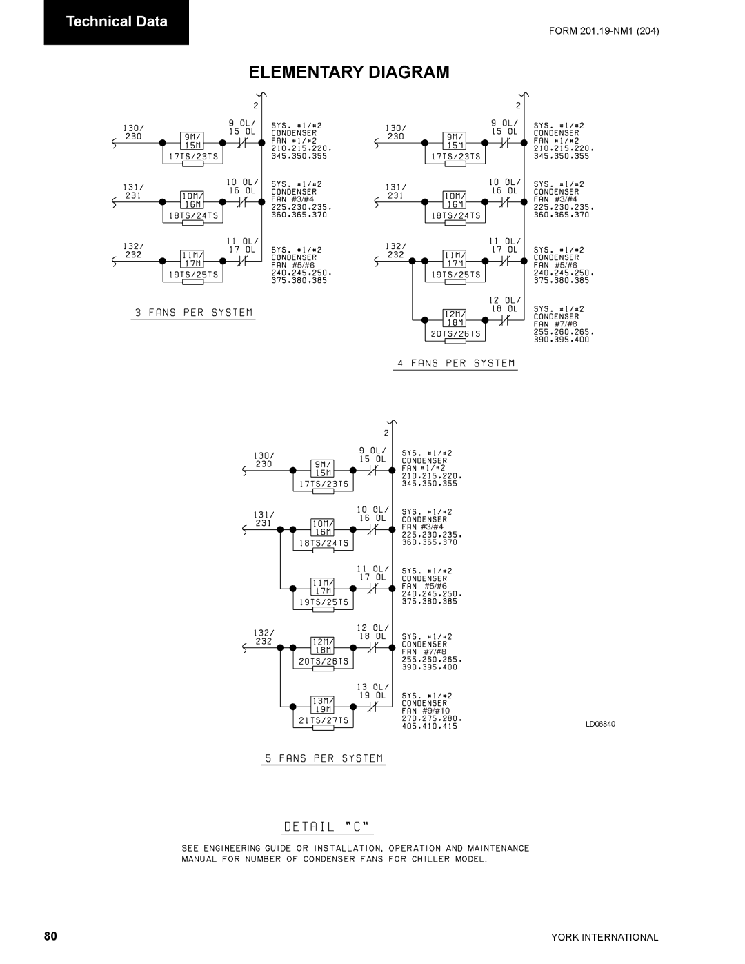
Technical Data
FORM
201.19-NM1
(204)
ELEMENTARY DIAGRAM
#3/#4
#3/#4
#5/#6
#5/#6
#7/#8
#3/#4
#5/#6
#7/#8
#9/#10
LD06840
80
YORK INTERNATIONAL
Page 79
Page 81
Page 80
Image 80
Page 79
Page 81
Contents
INSTALLATION, Operation & Maintenance New Release
AIR-COOLED Screw Liquid Chillers
Changeability of this Document
XXXXX-XXX
General Safety Guidelines
Safety Symbols
Table of Contents
Table of Contents CONT’D
Micro Panel Contents
Maintenance
List of Tables
Dimensions SI
List of Figures
General Chiller Information & Safety
Standards for Safety
General Access
Suitability for Application
Structural Support
Mechanical Strength
High Temperature and Pressure Cleaning
Rotating Parts
Sharp Edges
Refrigerants and Oils
Compressor
Product Description
General Description
Evaporator
Condenser
Power and Control Panel
Economizer
Oil Separator/System
Oil Cooling
Each power compartment contains
Control section contains
Options sections contain
Microprocessor Controls
Haxxx
Motor Protection Modules 2ACE
Current Overload
Thermal Overload
Current Imbalance Loaded & Unloaded/ Loss of Phase
Improper Phase Sequence
Motor Protector DIP Switch Setting
Ycas Style G, ACROSS-THE-LINE 60 HZ
Motor Protector DIP Switch Setting CONT’D
Ycas Style G, WYE Delta Start 60 HZ
321 126 279 109
Display
Multiple Point Power Connection Standard
Single-Point Power Connection without Circuit Protection
Program
Control Circuit Terminal Block
Following options provide added protection
Data
Basic Part Number
Product Identification Number PIN
Examples
Lifting Weights
Handling and Storage
Unit Rigging
Lifting Lugs
Installation
Installation
Installation
General Requirements
Water Treatment
D5 = 1.447 x L
Optional Flanges
Weld Flange
Units with Single-Point Power Supply Wiring
Alarm Contacts
Flow Switch
Remote Setpoint Offset Temperature
Remote Emergency Stop Device
Power Panel Layouts Typical
Power Panel Section
Option Panel Layout Typical
Option Panel Section
Description
Logic Section Layout
Hz Models
Logic Section Layout with Control Panel
Logic Section Layout with Control Panel
Customer Connections
Customer Connections
CB1, CB2, CB3
Commissioning
Switch Settings
Temperature Sensors
Programmed Settings
Compressor Heaters
System Switches
Interlocks
Start-up
Oil Pressure
This page intentionally left blank
Operation
This page intentionally left blank
Glycol Correction Example With YCAS0140
Technical Data
Glycol Correction Factors
MIN MAX
Temperature and Flows
Ycas
AIR on Condenser C
Number Temperature C Ycas
Model Leaving Water
Physical Data
English Units Model Number Ycas
SI Units Model Number Ycas
Operating Limitations and Sound Power Data
Operating Limitations English Units
Electrical Data
Suitable for ∆ Start Across-The-Line-Start
719
PROTECTION13 Standard Optional NF Disc SW2
Model System #1 System #2 Volts Compressor Data
Chiller FIELD-SUPPLIED Wiring Field Provided Power Supply
107
Suitable for Across-The-Line-Start
RLA X-LRA QTY
Compressor Data
Compressor Model and Voltage Code DXS45LA Motor Code a
Voltage Code
MAX Amps
Electrical Notes
Voltage Code
This page intentionally left blank
Wiring Diagram
Wiring Diagram ACROSS-THE-LINE Start
LD09233
Elementary Diagram
Elementary Diagram ACROSS-THE-LINE Start
Controlpower Supply
WYE-DELTA Start
Elementary Diagram WYE-DELTA Start
Elementary Diagram
Controlpower Supply
Power Panel System #1 Component Locations
Control Panel Component Location
Power Panel System #2 Component Locations
LD09241
ACE Motor Protector Module
Connection Diagram System Wiring
Compressor Terminal BOX
Elementary Diagram Control Circuit
#3/#4 #5/#6 #7/#8 #9/#10
This page intentionally left blank
Dimensions YCAS0130 YCAS0180 English
Models Dimension
Center of Gravity Alum
Dimensions YCAS0130 YCAS0180 SI
Model YCAS0130 0180 Dimensions SI
2573.0 1127.8
Dimensions YCAS0200 YCAS0230 English
Model YCAS0200 YCAS0230 Dimensions English
119.4 43.2 38.0
Dimensions YCAS0200 YCAS0230 SI
Model YCAS0200 YCAS0230 Dimensions SI
3032.8
Clearances
Weight Distribution and Isolator Mounting Positions
Aluminium and Black Fin Condenser Coils
Isolator MAX Load Defl Spring Type & Size
Color
Type Awmr Isolator Details
Isolator MAX Load Defl Type & Size
Color MAX. Load Deflection
Type
Copper FIN Condenser Coils Weight Distribution by Model LBS
Copper Fin Condenser Coils
544.3 29.7
50-553
250 1021.5
Aluminum FIN Coil Weight Distribution by Model LBS
Aluminium Fin Condenser Coils With Silencer Kit
100
101
Aluminum Fin Condenser Coils
102
Copper Fin Condenser Coils with Silencer Kit
103
104
105
106
107
Refrigerant Flow Diagram
108
Process and Instrumentation Diagram
109
Component Locations
110
Compressor Components
111
Compressor Components CONT’D
112
113
114
115
Part Name
116
System Startup Checklist
118
Power on Both System Switches OFF
Switch Switch Open Switch Closed Setting
119
SYS
120
121
Chiller Control Panel Programming and Data Access Keys
Introduction & Physical Description
123
System Switches 1
Internal Clock & Memory Backup Battery
Power Supply Board
Expansion Board
Relay Output Boards
125
126
127
Side View
TOP View
128
Remote Current Reset
Remote Start/Stop
Remote Setpoint Temperature Reset
129
130
Designation Description
131
132
133
134
135
Status KEY General Status Messages & Fault Warnings
Unit Switch OFF
Remote Controlled Shutdown
Schedule Shutdown
System Switches OFF
Anti-Recycle Timers
Anti-Coincidence Timers
Low Battery Warning
Power Failure Warning
Pump Down
Incorrect Refrigerant Warning
Incorrect Unit Type Warning
Suction Temperature Limiting
Low Ambient Temperature Cutout
High Ambient Temperature Cutout
Low Leaving Chilled Liquid Temperature Cutout
Flow Switch Open
High Discharge Temperature Cutout
High Oil Differential Pressure Cutout
140
Low Suction Pressure Cutout
High Oil Temperature Cutout
Low Oil Differential Pressure Cutout
High Compressor Motor Current Cutout
142
Low Evaporator Temperature Cutout R407C Only
143
Display Keys & Option Switches
144
145
MIN. Limit MAX. Limit
Switch 1 Water / Glycol Cooling Open
Switch 2 Ambient Temp. Range Low Ambient Cutout Open
Closed
146
Switch 3 Refrigerant Open
Switch 4 Unit Type Open
Dip Switch Physical Location and Setting
Switch 5 Motor Current Average option start-up Open
Switch 6 Heat Recovery Open
Switch 7 Expansion Valve Type Open
Switch 8 Standard Options Open
148
Print Keys
Ycas 2 System Models
Common Data
149
System Data
None
ISN
150
151
152
Chiller Data
153
154
155
156
157
Entry Keys
Keys
Setpoints Keys & Chilled Liquid Control
158
Load Timers
Slide Valve Control
Slide Valve Position
Compressor Starting & Loading Sequence
160
161
162
Clock Keys
163
164
165
166
Program KEY
High Discharge Pressure Cut-Out
High Discharge Pressure Unload Point
167
168
Low Leaving Liquid Temperature Cutout
High Motor Current Unload Point
Local/Remote Communications
Imperial/SI Units Display
Automatic/Manual Lead/Lag
169
Automatic/Manual Power Failure Restart
170
Program Value Mode Low Limit High Limit Default
171
Electronic Expansion Valve
172
EEV Operation
173
174
EEV Output
Program Value Mode LOW Limit High Limit Default
EEV Programming
Programmable Values Table MINIMUM/MAXIMUM
175
EEV Troubleshooting
176
Condenser FAN Control
177
178
OFF
Service Mode Programmable Values
179
Code PER Phase System Voltage RLA Thru CT
Ycas Style G, Across the Line Start 60 HZ
180
Chiller NO. Model Voltage Leads
Ycas Style G, Across the Line Start 60 HZ. Contd
181
Nameplate Leads Point Code System RLA PER Phase Voltage
Ycas Style G, WYE Delta Start 60 HZ
182
Model Voltage Chiller NO.
Ycas Style G, WYE Delta Start 60 HZ. Contd
183
184
Sensor Calibration Charts
Ambient Temperature Sensor
Oil & Discharge Temperature Sensors
Pressure Transducers
186
Control INPUTS/OUTPUTS
Digital Outputs
Analog Inputs
187
188
Digital Inputs
Analog Outputs
ISN Control
ISN Received Data
ISN Transmitted Data
189
ISN Transmitted Data Contd
190
191
ISN Operational and Fault Codes
192
193
194
Maintenance
Daily/Weekly Maintenance
195
Scheduled Maintenance
Chiller / Compressor Operating Log
FLA %
Compressor Unit Operation
196 Operating Log
Maintenance Requirements for York Ycas Screw Chillers
Procedure Weekly Quarterly SEMI-ANNUALLY Yearly Every
197
Hours
198
General Periodic Maintenance Checks Standard Units
Service Schedule Minor Service Major Service
Spare Parts
Recommended Spares
Recommended Compressor Oils
199
200
Troubleshooting Guide
Problem Possible Cause
201
Troubleshooting Guide CONT’D
Problem Possible Action
202
Limited Warranty York Americas Engineered Systems
ALL Warranties and Guarantees are Void if
Temperature Conversion Chart
Temperature Conversion Chart Actual Temperatures
Temperature Conversion Chart Differential Temperatures
Pressure Conversion Chart Gauge or Differential
ALL Rights Reserved
Top
Page
Image
Contents