3.3SYSTEM # DATA KEYS
Pressing one of the System # Data keys a number of times scrolls through displays of differential oil pressure (OIL), suction pressure (SP) and discharge pressure (DP), oil temperature, suction temperature (ST), discharge temperature (DT), saturated suction temperature, suction superheat, saturated discharge temperature, discharge superheat and compressor slide valve position.
Examples of these displays are shown where # is the appropriate system number:
S Y S | # O I L = | 1 7 6 |
| P S I G | ||||
S P = | 6 4 | D P = | 1 9 5 P S I G | |||||
|
|
|
|
|
|
|
| |
|
|
|
|
|
|
|
| |
S Y S | # | O I L | = | 1 | 5 | 7 | . 4 ° F | |
S T = | 3 1 . 0 D T = | 1 | 2 | 3 | . 2 ° F | |||
|
|
|
|
|
| |||
|
|
|
|
|
| |||
S # | S A T | S U C T | = | 3 2 | . 9 ° F | |||
S U C T S H E A T |
| = | 1 5 | . 0 ° F | ||||
|
|
|
|
|
|
|
|
|
|
|
|
|
|
|
|
|
|
S # S A T | D S C H = 1 3 0 . 0 | ° F | ||||||
D S C H S H E A T = | 5 4 | . 3 | ° F | |||||
|
| |||||||
|
| |||||||
S Y S # | S V S T E P = 3 7 | |||||||
| ||||||||
| ||||||||
S Y S # C O O L E R I N L E T | ||||||||
R E F R I G T E M P = | 2 8 | . 2 | ° F | |||||
|
|
|
|
|
|
|
|
|
The Evaporator Inlet Temp. display will only appear if the chiller is selected for R407C.
Temperatures and pressures are either measured directly by transducers and temperature sensors, or computed from these measurements as follows:
Saturated discharge and suction temperatures are computed by converting measured pressure to tem- perature.
Slide Valve Position is computed based on the number of loading steps that the micro has sent to the slide valve solenoid in the form of a voltage signal. To the microprocessor, STEP 0 = fully unloaded and STEP 75 = fully loaded.
FORM
Slide valve position isAPPROXIMATE and should be used for reference only. Under actual conditions the com- pressor may be fully loaded between 8 step 60 - 75 and fully unloaded between step 0 - 35.
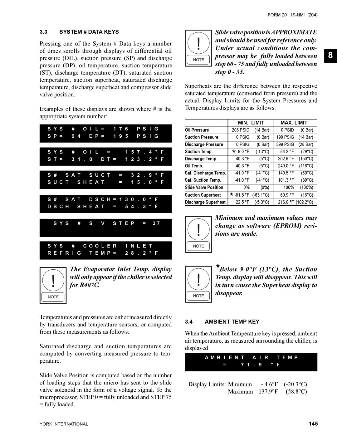
Superheats are the difference between the respective saturated temperature (converted from pressure) and the actual. Display Limits for the System Pressures and Temperatures displays are as follows:
|
| MIN. LIMIT | MAX. LIMIT | |||||
| Oil Pressure | 208 PSID | (14 Bar) | 0 PSID | (0 Bar) | |||
Suction Pressure | 0 PSIG | (0 Bar) | 199 PSIG | (14 Bar) | ||||
Discharge Pressure | 0 PSIG | (0 Bar) | 399 PSIG | (28 Bar) | ||||
Suction Temp. | * 9.0 °F | 84.2 | °F | (29°C) | ||||
Discharge Temp. | (5°C) | 302.6 | °F | (150°C) | ||||
40.3 | °F | |||||||
Oil Temp. | 40.3 | °F | (5°C) | 240.0 | °F | (116°C) | ||
Sat. Discharge Temp. | 140.5 | °F | (60°C) | |||||
Sat. Suction Temp. | 101.3 | °F | (39°C) | |||||
Slide Valve Position | 0% | (0%) | 100% | (100%) | ||||
Suction Superheat | * | °F | 60.9 | °F | (16°C) | |||
Discharge Superheat | °F | 216.0 | °F (102.2°C) | |||||
22.5 | ||||||||
Minimum and maximum values may change as software (EPROM) revi- sions are made.
*Below 9.0°F (13°C), the Suction Temp. display will disappear. This will in turn cause the Superheat display to
disappear.
3.4AMBIENT TEMP KEY
When the Ambient Temperature key is pressed, ambient air temperature, as measured surrounding the chiller, is displayed.
A M B I E N T | A I R T E M P | |||
= | 7 | 1 | . 9 ° F | |
|
|
| ||
Display Limits: Minimum | - 4.6°F | |||
| Maximum | 137.9°F | (58.8°C) | |
YORK INTERNATIONAL | 145 |