FORM
8.8 CONDENSER FAN CONTROL
The chiller is equipped with 8 or 10 condenser fans, with 4 or 5 fans per system as given below. Fan control is via Outside Ambient Temperature (OAT) and Discharge Pressure (DP). There are 4 or 5 stages of fan control, utilizing 3 outputs per system. The fan stages will work according to Table 3 and 4 depending on the number of fans per system. There will be a variable delay between all fan stages. The delay between turning on fan stages is based on the ambient temperature. The time is ramped from 30 seconds at 10ºF
Condenser fan ON conditions are governed solely by the Discharge Pressure (DP). When the DP rises above 230 PSIG, fan stage 1 is activated. From here, subsequent fan stages are activated as the DP rises in increments of 10 - 20 PSIG. The system will remain at the highest fan stage reached unless the OFF conditions are satisfied.
Condenser fan OFF conditions are governed by both the DP and OAT. Fan staging will be decreased from the highest fan stage reached if both the DP and OAT requirements are met. For example, if a system is at a fan stage of 4, and the DP falls under 205 PSIG and the OAT drops below 75ºF (24ºC), the fan stage will be reduced to 3.
Tables 3 and 4 describe fan operation and contactor data for the fans involved in each fan stage. SYS 1 uses relay board #1. SYS 2 uses relay board #2.
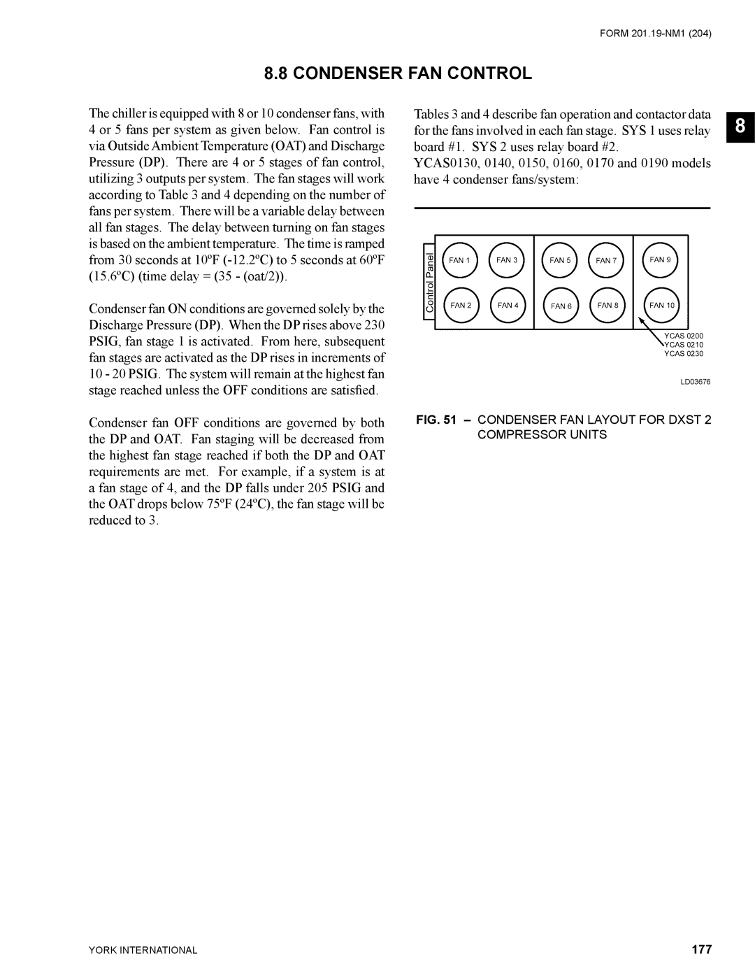
YCAS0130, 0140, 0150, 0160, 0170 and 0190 models have 4 condenser fans/system:
LD03676
FIG. 51 – CONDENSER FAN LAYOUT FOR DXST 2 COMPRESSOR UNITS
8
YORK INTERNATIONAL | 177 |