Installation
FORM
Pipework and fittings must be separately supported to prevent any loading on the evaporator. Flexible con- nections are recommended which will also minimize transmission of vibrations to the building. Flexible connections must be used if the unit is mounted on
Pipework and fittings immediately next to the evapora- tor should be readily
The evaporator must be protected by a strainer, pref- erably of 30 mesh, fitted as close as possible to the liquid inlet connection, and provided with a means of local isolation.
The evaporator must not be exposed to flushing veloci- ties or debris released during flushing. It is recommended that a suitably sized
Thermometer and pressure gauge connections should be provided on the inlet and outlet connections of each evaporator.
Drain and air vent connections should be provided at all low and high points in the pipework to permit drainage of the system and to vent any air in the pipes.
Liquid systems at risk of freezing, due to low ambient temperatures, should be protected using insulation and heater tape and/or a suitable glycol solution. The liquid pump(s) must also be used to ensure liquid is circulated when the ambient temperature approaches freezing point. Insulation should also be installed around the evaporator nozzles. Heater tape of 21 watts per meter under the insulation is recommended, supplied inde- pendently and controlled by an ambient temperature thermostat set to switch on at 37°F (21°C) above the freezing temperature of the liquid.
The liquid circulation pump must be controlled by the unit. This will ensure that when the liquid temperature falls within 3° or 5°F (2° or 3°C) of freezing, the pump will start.
The evaporator is protected by heater mats under the in- sulation which are supplied from the unit control system power supply. During risk of freezing the control system should be powered to provide the freeze protection func- tion unless the liquid systems have been drained.
Any debris left in the water pipework between the strainer and evaporator could cause serious damage to the tubes in the evaporator and must be avoided. The installer/user must also ensure that the quality of the water in circulation is adequate, without any dissolved gases which can cause oxidation of steel parts within the evaporator.
WATER TREATMENT
The unit performance given in the Design Guide is based on a fouling factor of 0.00025 ft2hr°F/Btu (0.044m2/hr °C/kW). Dirt, scale, grease and certain types of water treatment will adversely affect the heat exchanger sur- faces and therefore unit performance. Foreign matter in the water system(s) can increase the heat exchanger pressure drop, reducing the flow rate and causing po- tential damage to the heat exchanger tubes.
Aerated, brackish or salt water is not recommended for use in the water system(s). YORK recommends that a water treatment specialist is consulted to determine the proposed water composition will not affect the evapo- rator materials of carbon steel and copper. The pH value of the water flowing through the evaporator must be kept between 7 and 8.5.
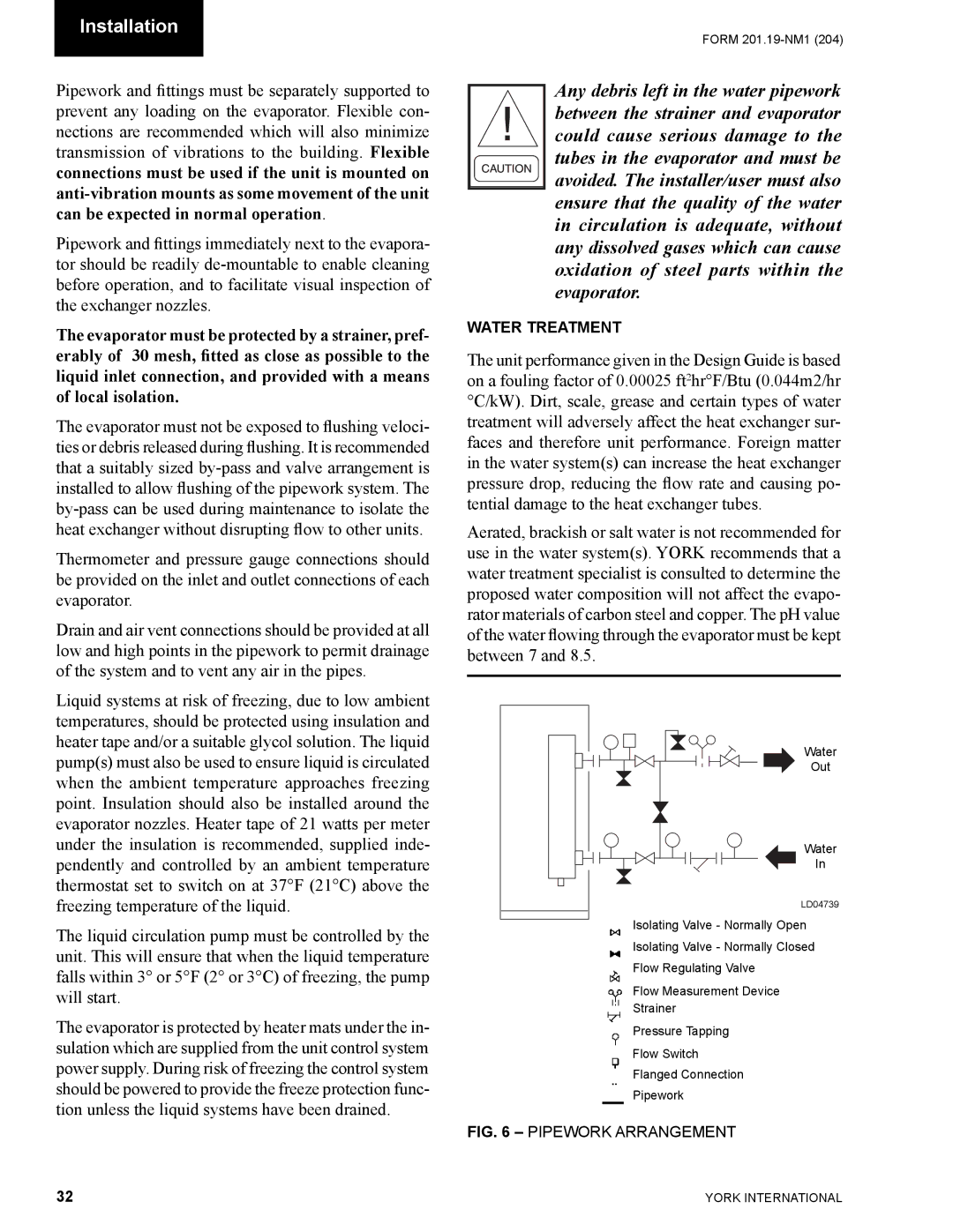
Water
Out
Water
In
LD04739
Isolating Valve - Normally Open
Isolating Valve - Normally Closed
Flow Regulating Valve
Flow Measurement Device
Strainer
Pressure Tapping
Flow Switch
Flanged Connection
Pipework
FIG. 6 – PIPEWORK ARRANGEMENT
32 | YORK INTERNATIONAL |