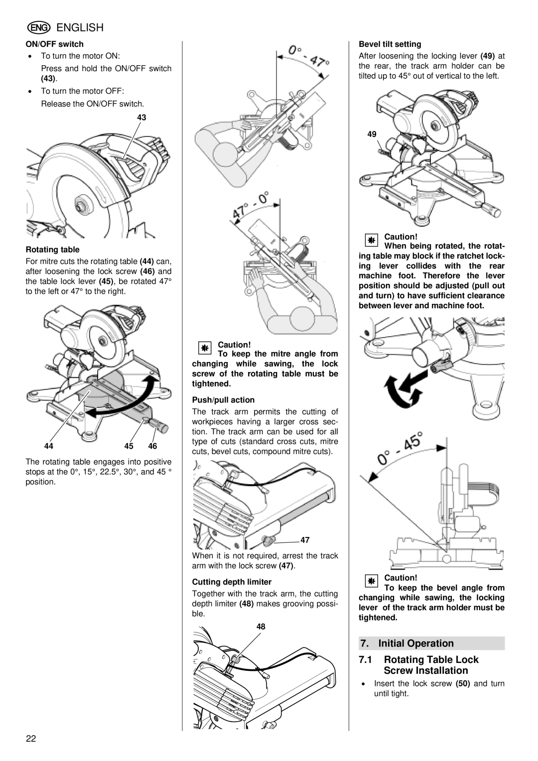
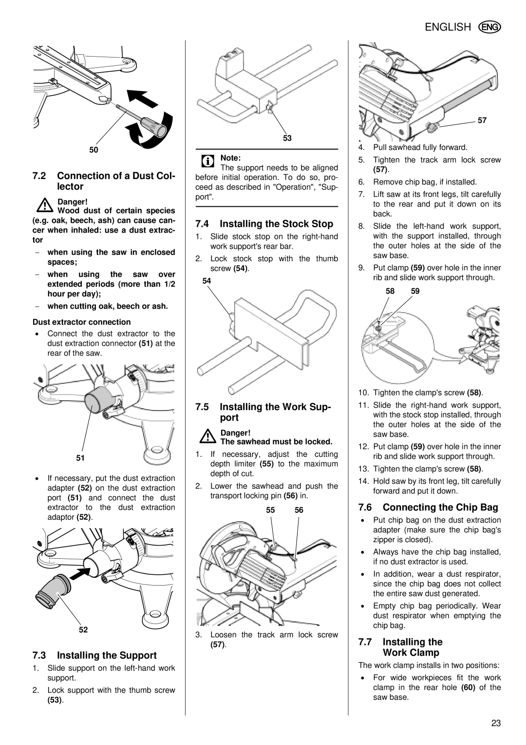
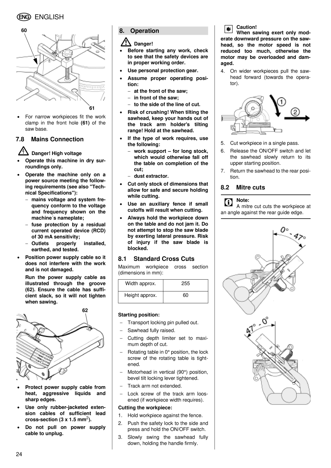
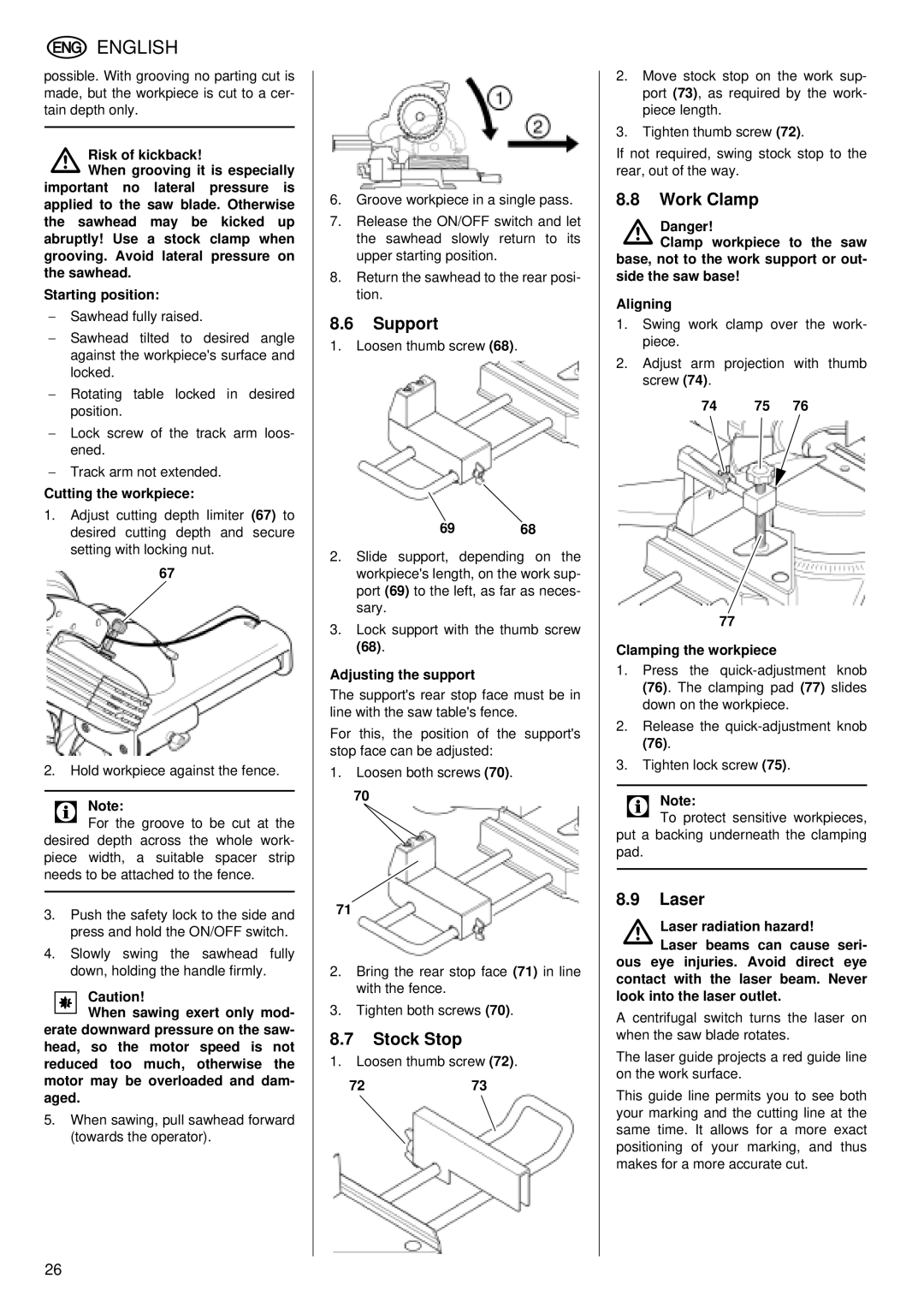
Metabo KGS 255 Plus Machine Cleaning, Machine storage, Maintenance, Tips and Tricks, Repairs

Page 29

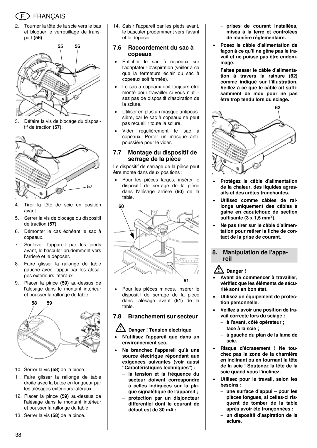
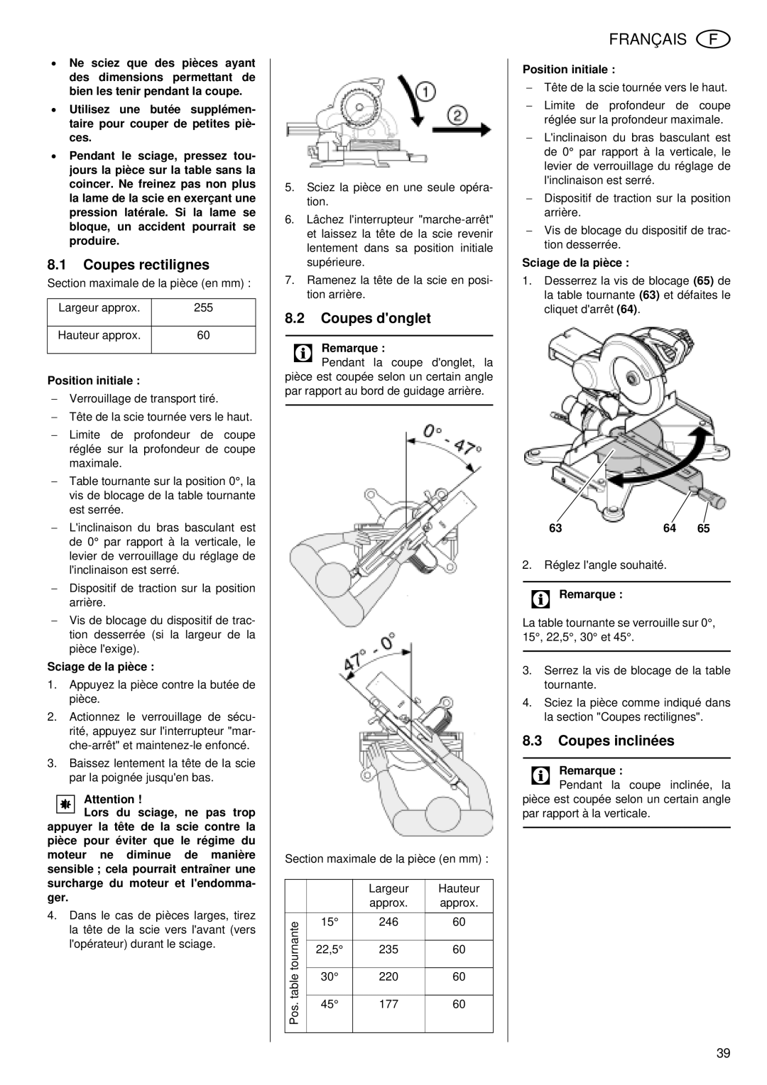
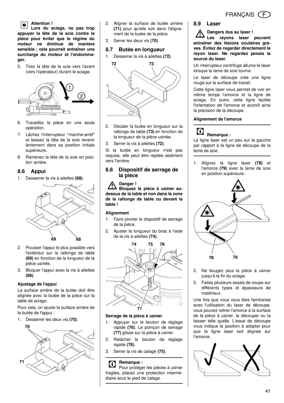
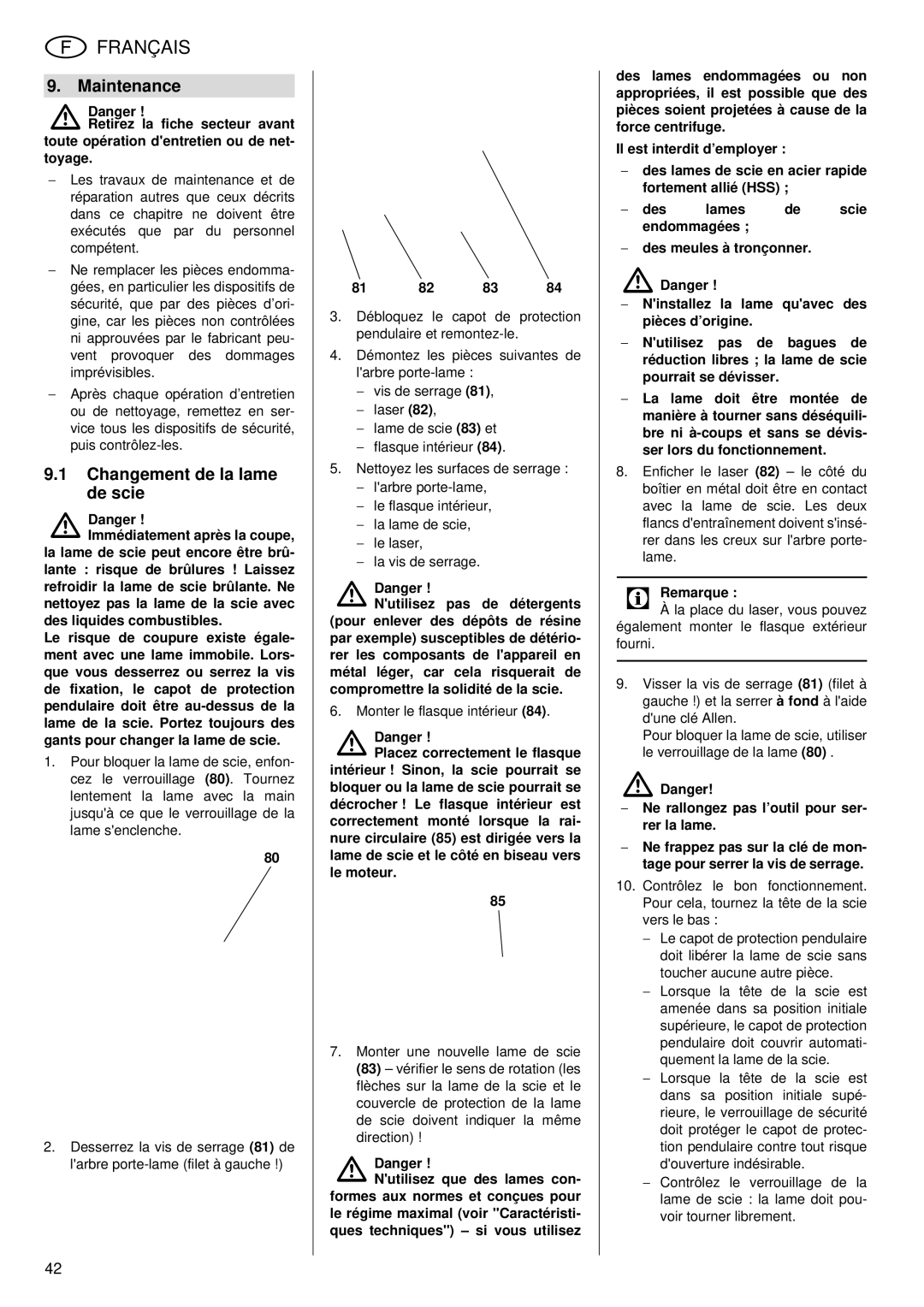
93 94

9.5Machine Cleaning

Remove chips and saw dust with brush or vacuum from:

setting devices;

the operating elements;

motor vent slots;

space below table insert.

9.6Machine storage

ADanger!

Store the saw in such way that it cannot be used or tampered with by unauthorised persons.

Make sure that nobody can get injured by the stored machine.

A Caution!

Do not store saw unprotected outdoors or in damp environ- ment.

Observe the permissible ambient conditions (see "Technical Speci- fications").

9.7Maintenance

Prior to every use

Remove saw dust and chips with vacuum or brush.

Check power cable and power cable plug for damage; if necessary, have damaged parts replaced by a quali- fied electrician.

Check all moving parts to see that they can move freely across their whole range of travel.

Periodically, depending on operating conditions

Check all screwed joints, retighten if necessary.

Check pull-back springs of the saw- head (the sawhead must return by spring power to its upper starting position), replace if necessary.

10. Tips and Tricks

For long stock use suitable supports on both sides of the saw.

When performing bevel cuts, hold the workpiece on the right side of the saw blade.

Use auxiliary fence when sawing small cut-offs (this may be a suitable board, fastened with four screws to the fence).

When cutting warped stock, place the convex side of the bow against the fence.

Do not cut stock standing on edge; always place it flat on the rotating table.

Keep the supporting surfaces clean

– in particular, remove resin residue with a suitable cleaning and mainte- nance spray.

11. Available Accessories

For special tasks the following accesso- ries are available at your specialised dealer – see back cover for illustrations:

AMulti-Suction Adapter

To connect different dust collection attachments.

BTable Extension

Required when cutting long stock; folds up to save space.

CWork Stand

For a secure machine stand and optimal working height;

folding, ideal for mobile use.

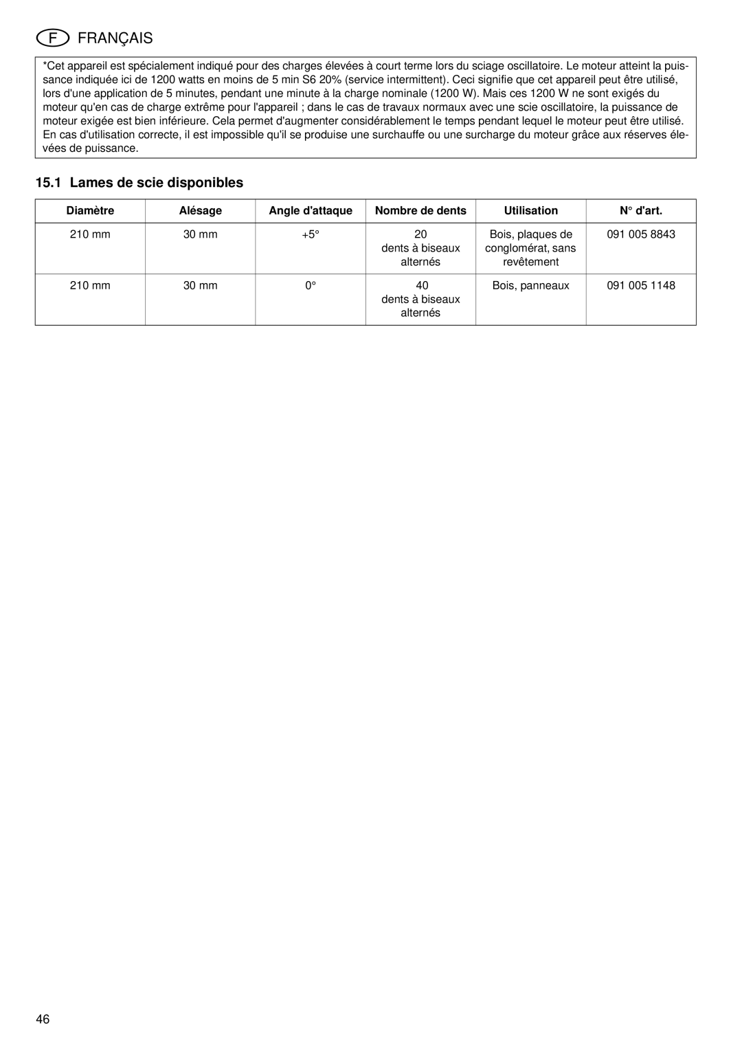
DTCT saw blade 210 x 2.0 / 1.4 x 30 20 alternate bevel teeth

for wood and non-laminated parti- cle board.

ETCT saw blade 210 x 2.4 / 1.8 x 30 40 alternate bevel teeth

For wood and panels.

12.Repairs

ADanger!

Repairs to electric tools must be carried out by qualified electri- cians only!

Electric tools in need of repair can be sent to the Service Centre of your coun- try. Refer to the spare parts list for the address.

Please attach a description of the fault to the electric tool.

ENGLISH

13. Environmental Protection

The machine's packing can be 100% recycled.

Worn out power tools and accessories contain considerable amounts of valua- ble raw and rubber materials, which can be recycled.

These instructions are printed on paper produced with elemental chlorine free bleaching process.

14. Troubleshooting Guide

This section describes problems and malfunctions which you should be able to resolve yourself. If the measures described here do not solve your prob- lem, see under "Repairs".

ADanger!Many accidents happen partic- ularly in connection with problems and faults. Therefore please note:

Always unplug before servicing.

Check to see that all safety devices are operational after each fault service.

Motor does not run

No mains voltage

Check cables, plug, outlet and mains fuse.

No crosscut function

Transport locking pin engaged:

Pull transport locking pin out. Safety lock engaged:

Actuate the safety lock.

Only little sawing performance

Saw blade blunt (possibly tempering marks on blade body):

Saw blade not suitable for material being cut (see chapter "Technical Specifica- tions");

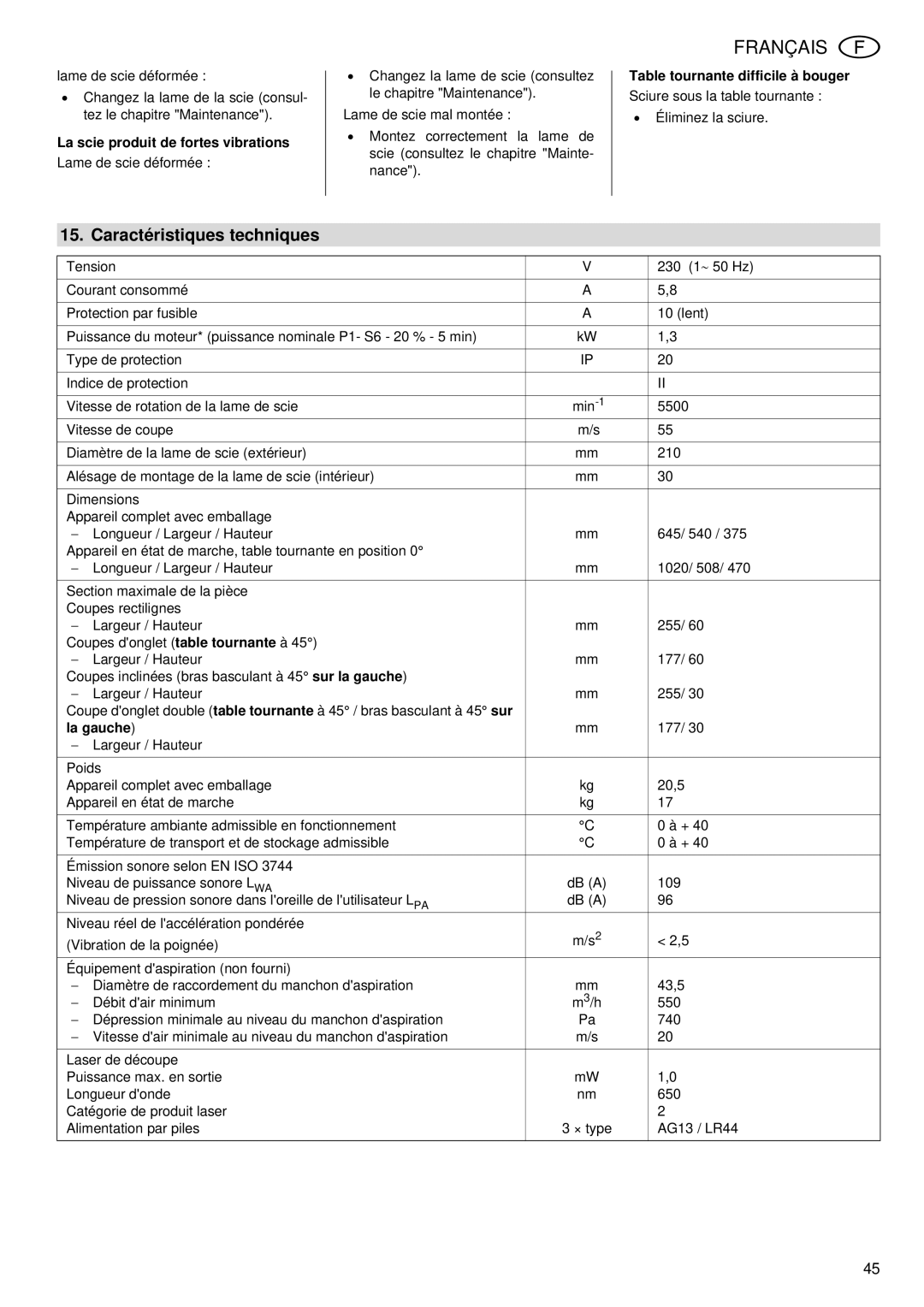
Saw blade warped:

Replace saw blade (see chapter "Maintenance").

Saw vibrates heavily

Saw blade warped:

Replace saw blade (see chapter "Maintenance").

Saw blade incorrectly mounted:

Mount saw blade correctly (see chapter "Maintenance").

Stiffness of rotating table

Saw dust build-up under rotating table:

Remove saw dust.

29
Image 29
Contents 115 172 8754/ 3506 KGS 255 PlusKGS 255 Plus 1321 Das Gerät im Überblick LieferumfangWerkzeug GeräteunterlagenZuerst lesen InhaltsverzeichnisSicherheit Bestimmungsgemäße Verwendung Allgemeine Sicherheits- hinweiseAVerletzungsgefahr an bewegli- chen Teilen BGefahr durch ElektrizitätASchnittgefahr auch bei stehen- dem Schneidwerkzeug CEinzugsgefahrAufstellung und Trans- port Symbole auf dem GerätSicherheitseinrichtungen Das Gerät im Einzelnen Besondere Produkteigen- schaftenAuflage montieren Anschluss einer Späne- absauganlageLängenanschlag montie- ren Tischverlängerung mon- tierenWerkstückspann- vorrichtung montieren Anschluss des Späne- sacksNetzanschluss BedienungGehrungsschnitte Gerade SchnitteGeneigte Schnitte AusgangsstellungNutensägen DoppelgehrungsschnitteLängenanschlag AuflageWerkstückspann- vorrichtung LaserInnenflansch 84 aufstecken Sägeblatt wechselnAuswechseln der Batte- rien Justierungen Tischeinlage wechselnGerät reinigen Gerät aufbewahrenWartung Probleme und StörungenTipps und Tricks Lieferbares Zubehör550 Technische DatenBohrung Spanwinkel Lieferbare SägeblätterVerwendung Bestell-Nr HolzTools Components and Parts standard deliveryRetractable blade guard Track arm holder 45-Position Machine documentsSafety Specified Conditions of Use Table of ContentsGeneral Safety Instruc- tions Please read firstSymbols on the Machine Installation and Trans- port Safety DevicesSpecial Product Features Machine DetailsON/OFF switch Initial Operation Rotating Table Lock Screw InstallationBevel tilt setting Rotating tableInstalling the Stock Stop Installing the SupportInstalling the Work Sup- port Connecting the Chip BagOperation Mains ConnectionStandard Cross Cuts Mitre cutsGrooving Bevel CutsCompound Mitre Cuts Support Adjusting the supportStock Stop Work ClampChanging the Saw Blade Care and MaintenanceAligning the marking ADanger Unplug before servicingReplacing the Table Insert AdjustmentsReplacing the Batteries Maintenance Machine CleaningAvailable Accessories Troubleshooting GuideMitre cuts rotating table Technical SpecificationsTeeth Available Saw BladesOutillage Vue générale de lappareilfournitureDocuments fournis avec lappareil Instructions dutilisation Liste des pièces de rechangeLire impérativement Table de MatièresSécurité Utilisation conforme aux prescriptions Consignes générales de sécuritéBDangers dus à lélectricité APrincipaux dangersADanger de blessures dues à des pièces mobiles CRisques daccrochageDispositifs de sécurité Symboles sur lappareilInstallation et transport Lappareil en détail Propriétés du produitInterrupteur marche-arrêt Table tournanteMontage de lappui Raccordement dun sys- tème daspiration de la sciureMontage de la butée en longueur Montage de la rallonge de tableMontage du dispositif de serrage de la pièce Raccordement du sac à copeauxBranchement sur secteur Manipulation de lappa- reilCoupes donglet Coupes rectilignesCoupes inclinées Position initialeScier des rainures Coupes donglet doubleSection maximale de la pièce en mm Largeur Hauteur Approx Incl. bras bascul 22,5Dispositif de serrage de la pièce AppuiButée en longueur Monter le flasque intérieur Changement de la lame de scieRéglages Remplacement des pilesRemplacement du sup- port de table Nettoyage de lappareil Accessoires disponiblesConservation de lappa- reil Conseils et trucsLa scie produit de fortes vibrations Caractéristiques techniquesTable tournante difficile à bouger La gauche30 mm Lames de scie disponibles091 005 RevêtementUtensili Visione dinsieme dellapparecchio ambito della fornituraDocumentazione sullapparecchio Istruzioni per luso Elenco dei pezzi di ricambioIstruzioni obbligatorie SommarioSicurezza Utilizzo appropriato Istruzioni generali per la sicurezzaAPericolo di tagli anche con utensili da taglio fermi BPericolo di scosse elettricheCPericolo di trascinamento APericolo causato da protezione personale insufficientePosizionamento e tra- sporto Simboli sullapparecchioDispositivi di sicurezza Lapparecchio in detta- glio Caratteristiche partico- lari del prodottoMontaggio del supporto per il pezzo da tagliare Collegamento di un impianto di aspirazione dei trucioliMontaggio della battuta di arresto longitudinale Montaggio della prolunga del bancoMontaggio del disposi- tivo di blocco del pezzo Collegamento del sac- chetto dei trucioliCollegamento elettrico UsoTagli obliqui Tagli dirittiTagli inclinati Posizione di partenzaScanalature Tagli ad angolo doppioInclinazione 22,5 Vato. Mantenere una distanza suffi- ciente dalla lamaDispositivo di blocco del pezzo Supporto per il pezzo da tagliareBattuta di arresto longitu- dinale Sostituzione della lama ManutenzioneInfilare la flangia interna Controllare il funzionamento abbas- sando il gruppo segaSostituzione dellinserto Sostituzione delle batte- rieRegolazioni Pulizia dellapparecchioProblemi e anomalie Accessori disponibili su richiestaCustodia dellapparec- chio Suggerimenti e consigliDati tecnici Diametro Foro Angolo Numero denti Impiego Dordine Lame disponibiliHW 210 x 2,0 / 1,4 x 30 20 W 091 005 091 005 8835 3000 mm 091 005 8827 1600 mm091 005 HW 210 x 2,4 / 1,8 x 30 40 W