CHAPTER 4: ATTACHING A CONSOLE
4.3PINOUT DESCRIPTIONS
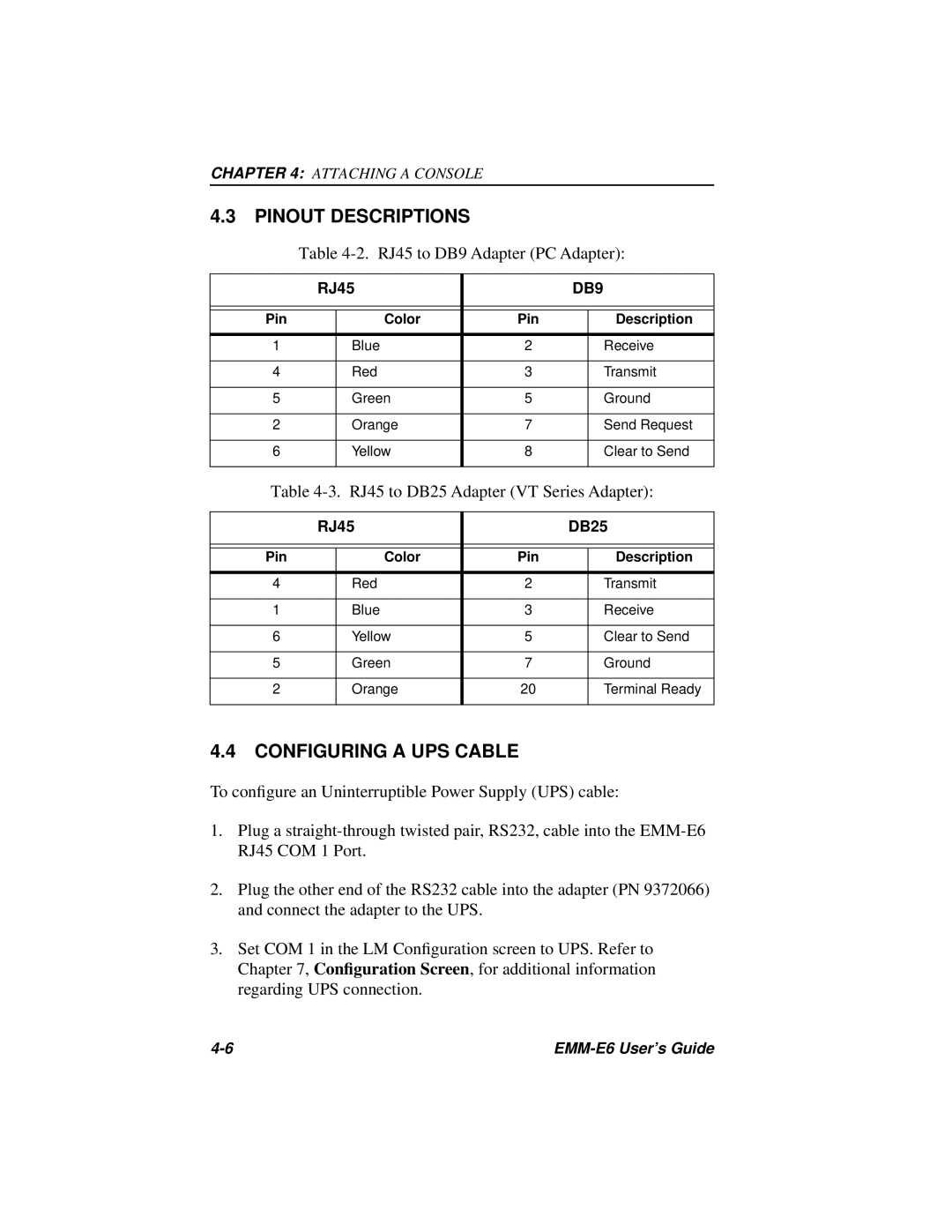
Table 4-2. RJ45 to DB9 Adapter (PC Adapter):
| RJ45 |
| DB9 | ||
|
|
|
|
|
|
|
|
|
|
|
|
Pin |
| Color | Pin |
| Description |
|
|
|
|
|
|
1 |
| Blue | 2 |
| Receive |
|
|
|
|
|
|
4 |
| Red | 3 |
| Transmit |
|
|
|
|
|
|
5 |
| Green | 5 |
| Ground |
|
|
|
|
|
|
2 |
| Orange | 7 |
| Send Request |
|
|
|
|
|
|
6 |
| Yellow | 8 |
| Clear to Send |
|
|
|
|
|
|
Table 4-3. RJ45 to DB25 Adapter (VT Series Adapter):
| RJ45 |
| DB25 | ||
|
|
|
|
|
|
|
|
|
|
|
|
Pin |
| Color | Pin |
| Description |
|
|
|
|
|
|
4 |
| Red | 2 |
| Transmit |
|
|
|
|
|
|
1 |
| Blue | 3 |
| Receive |
|
|
|
|
|
|
6 |
| Yellow | 5 |
| Clear to Send |
|
|
|
|
|
|
5 |
| Green | 7 |
| Ground |
|
|
|
|
|
|
2 |
| Orange | 20 |
| Terminal Ready |
|
|
|
|
|
|
4.4CONFIGURING A UPS CABLE
To configure an Uninterruptible Power Supply (UPS) cable:
1.Plug a
2.Plug the other end of the RS232 cable into the adapter (PN 9372066) and connect the adapter to the UPS.
3.Set COM 1 in the LM Configuration screen to UPS. Refer to Chapter 7, Configuration Screen, for additional information regarding UPS connection.
|