INSTALLATION
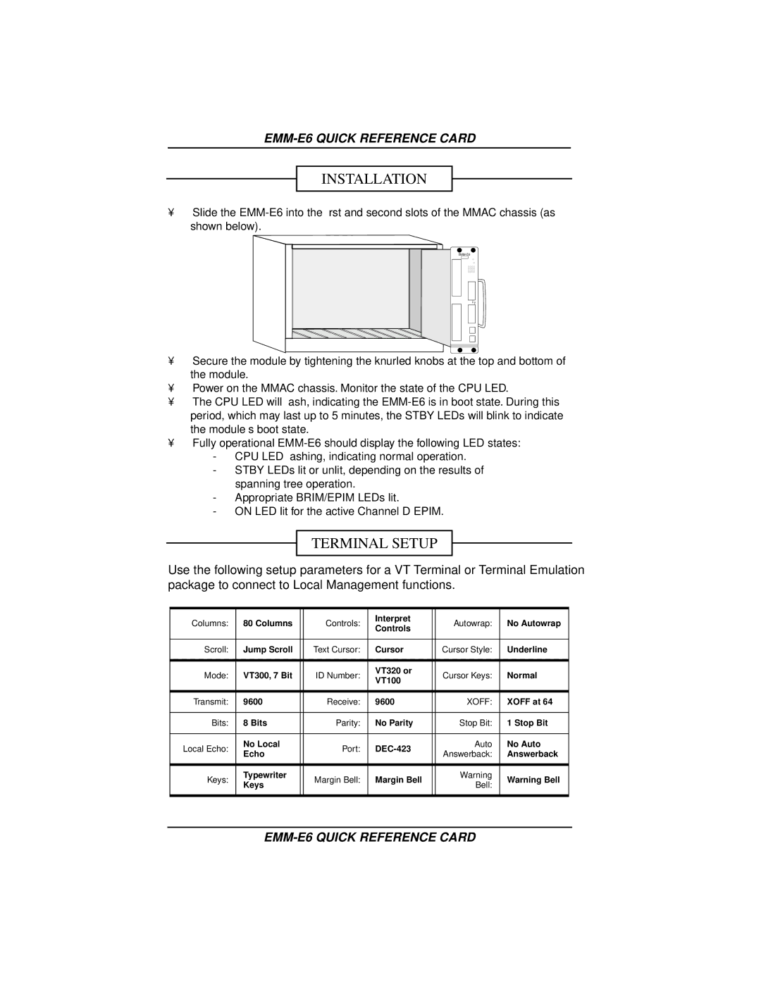
•Slide the
•Secure the module by tightening the knurled knobs at the top and bottom of the module.
•Power on the MMAC chassis. Monitor the state of the CPU LED.
•The CPU LED will flash, indicating the
•Fully operational
-CPU LED flashing, indicating normal operation.
-STBY LEDs lit or unlit, depending on the results of spanning tree operation.
-Appropriate BRIM/EPIM LEDs lit.
-ON LED lit for the active Channel D EPIM.
TERMINAL SETUP
Use the following setup parameters for a VT Terminal or Terminal Emulation package to connect to Local Management functions.
Columns: | 80 Columns |
| Controls: | Interpret |
| Autowrap: | No Autowrap |
| Controls |
| |||||
|
|
|
|
|
|
| |
|
|
|
|
|
|
|
|
Scroll: | Jump Scroll |
| Text Cursor: | Cursor |
| Cursor Style: | Underline |
|
|
|
|
|
|
|
|
Mode: | VT300, 7 Bit |
| ID Number: | VT320 or |
| Cursor Keys: | Normal |
| VT100 |
| |||||
|
|
|
|
|
|
| |
|
|
|
|
|
|
|
|
Transmit: | 9600 |
| Receive: | 9600 |
| XOFF: | XOFF at 64 |
|
|
|
|
|
|
|
|
Bits: | 8 Bits |
| Parity: | No Parity |
| Stop Bit: | 1 Stop Bit |
|
|
|
|
|
|
|
|
Local Echo: | No Local |
| Port: |
| Auto | No Auto | |
Echo |
|
| Answerback: | Answerback | |||
|
|
|
|
| |||
|
|
|
|
|
|
|
|
Keys: | Typewriter |
| Margin Bell: | Margin Bell |
| Warning | Warning Bell |
Keys |
|
| Bell: | ||||
|
|
|
|
|
| ||
|
|
|
|
|
|
|
|