Chapter 5 Connecting the Management Interfaces and Performing Initial System Configuration
Initial System Configuration
Each group of related parameters is prefaced by a question, asking whether you want to enter the menu. To skip the menu, answer no (“n”) to the question.
EXAMPLE:
Would you like to enter the SNMP configuration menu? n
•To abort the setup dialog at any point without making any configuration changes, press ^c. All changes already entered will be lost, with the exception of time settings.
Step 1: Configuring Initial Settings
Verify the following initial settings for the SCE 2000:
•IP address
•Subnet mask
•Default gateway
All values are Internet addresses of the form ‘X.X.X.X’, where each letter corresponds to a decimal number between 0 and 255.
To configure the initial settings, complete the following steps:
Step 1 The current IP address is displayed.
•To accept the displayed value, press Enter.
•To change the value, type the desired value in the format “x.x.x.x” and press Enter. Step 2 The current subnet mask is displayed.
•To accept the displayed value, press Enter.
•To change the value, type the desired value in the format “x.x.x.x” and press Enter. Step 3 The current IP address of the default gateway is displayed.
•To accept the displayed value, press Enter.
•To change the value, type the desired value in the format “x.x.x.x” and press Enter.
EXAMPLE:
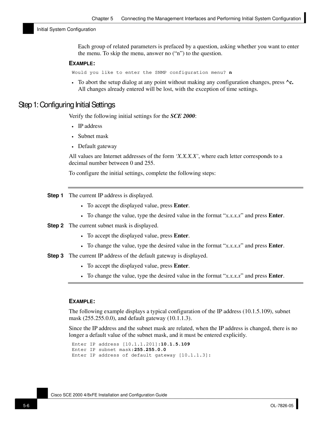
The following example displays a typical configuration of the IP address (10.1.5.109), subnet mask (255.255.0.0), and default gateway (10.1.1.3).
Since the IP address and the subnet mask are related, when the IP address is changed, there is no longer a default value of the subnet mask, and it must be entered explicitly.
Enter IP address [10.1.1.201]:10.1.5.109
Enter IP subnet mask:255.255.0.0
Enter IP address of default gateway [10.1.1.3]:
Cisco SCE 2000 4/8xFE Installation and Configuration Guide
| ||
|
|
|