Chapter 4 Installation and Maintenance
Power Supply Overview ![]()
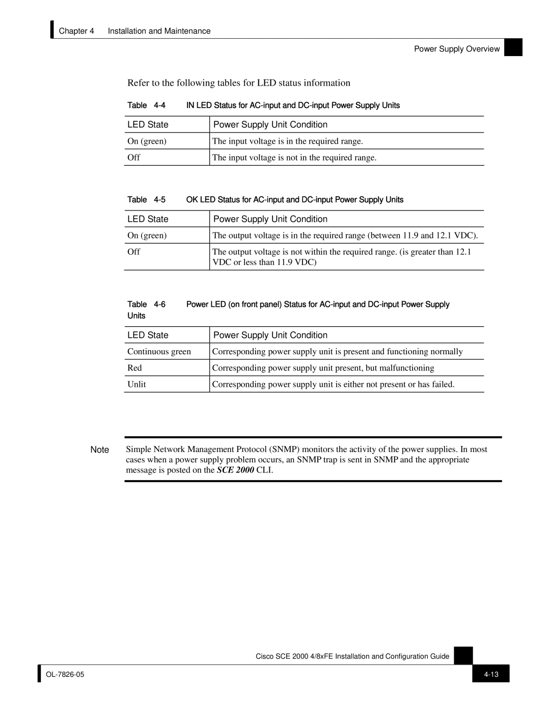
Refer to the following tables for LED status information
Table
LED State |
| Power Supply Unit Condition |
|
|
|
On (green) |
| The input voltage is in the required range. |
|
|
|
Off |
| The input voltage is not in the required range. |
|
|
|
Table | OK LED Status for | |
|
|
|
LED State |
| Power Supply Unit Condition |
|
|
|
On (green) |
| The output voltage is in the required range (between 11.9 and 12.1 VDC). |
|
|
|
Off |
| The output voltage is not within the required range. (is greater than 12.1 |
|
| VDC or less than 11.9 VDC) |
|
|
|
Table
LED State | Power Supply Unit Condition |
|
|
Continuous green | Corresponding power supply unit is present and functioning normally |
|
|
Red | Corresponding power supply unit present, but malfunctioning |
|
|
Unlit | Corresponding power supply unit is either not present or has failed. |
|
|
Note Simple Network Management Protocol (SNMP) monitors the activity of the power supplies. In most cases when a power supply problem occurs, an SNMP trap is sent in SNMP and the appropriate message is posted on the SCE 2000 CLI.
Cisco SCE 2000 4/8xFE Installation and Configuration Guide
| ||
|
|
|
