Chapter 6 Cabling the Line Ports and Completing the Installation
Connecting the line ports to the network
Cabling Diagrams
Before beginning, find the appropriate cabling diagram for the topology in your installation:
•Single SCE 2000 topologies
•Single Link: Inline Topology (on page
•Single Link:
•Dual Link: Single SCE 2000 Topologies (on page
•Dual SCE 2000 topologies (cascaded)
•Dual Link: Two SCE 2000s Topology (on page
Note When installing a cascaded system, it is extremely important to follow the sequence of procedures outlined in the section Installing a Cascaded System (on page
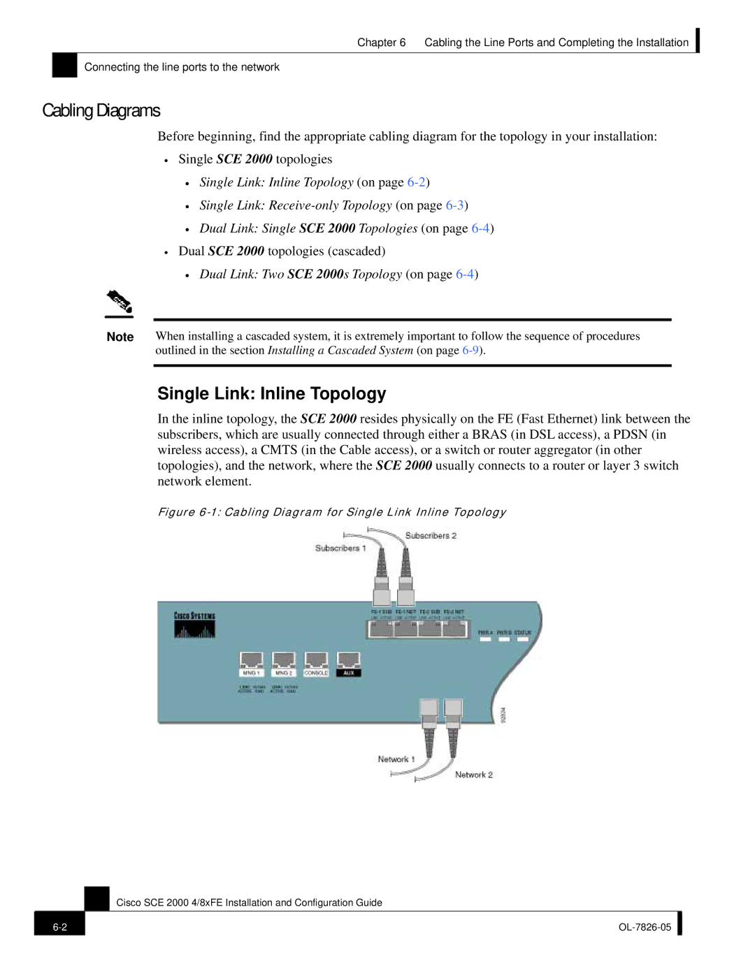
Single Link: Inline Topology
In the inline topology, the SCE 2000 resides physically on the FE (Fast Ethernet) link between the subscribers, which are usually connected through either a BRAS (in DSL access), a PDSN (in wireless access), a CMTS (in the Cable access), or a switch or router aggregator (in other topologies), and the network, where the SCE 2000 usually connects to a router or layer 3 switch network element.
Figure 6-1: Cabling Diagram for Single Link Inline Topology
Cisco SCE 2000 4/8xFE Installation and Configuration Guide
| ||
|
|
|