Cisco Systems SCE 2000 4/8xFE manual Dual Link Single SCE 2000 Topologies, SCE 2000 #1

Models: SCE 2000 4/8xFE

1 131
Download 131 pages 39.66 Kb
Page 90
Image 90
Dual Link: Single SCE 2000 Topologies

Chapter 6 Cabling the Line Ports and Completing the Installation

Connecting the line ports to the network

Dual Link: Single SCE 2000 Topologies

In this topology, one SCE 2000 is connected to two full duplex, FE links. The SCE 2000 may be either inline, to support both monitoring and traffic control functionality, or receive-only for traffic monitoring functionality only.

When one SCE 2000 supports two links, the first pair of ports (FE-1 SUB/NET) is connected to one link, while the second pair of ports (FE-2 SUB/NET) is connected to the second link as follows;

FE-1 SUB: Link 1, Subscriber side

FE-1 NET: Link 1, Network side

FE-2 SUB: Link 2, Subscriber side

FE-2 NET: Link 2, Network side

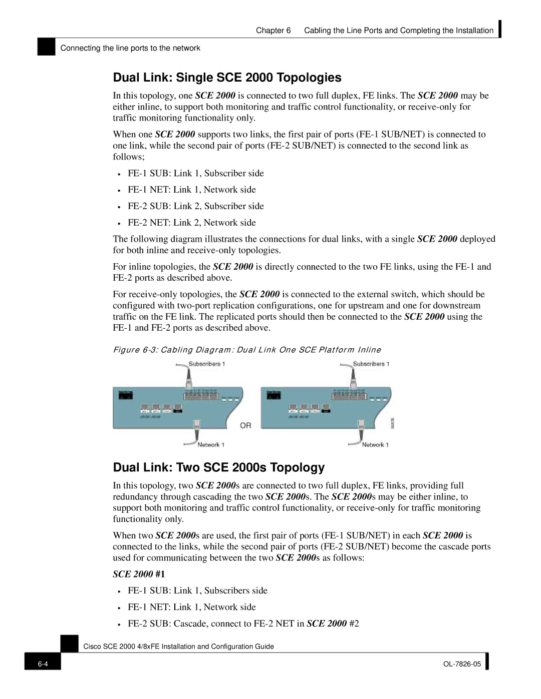
The following diagram illustrates the connections for dual links, with a single SCE 2000 deployed for both inline and receive-only topologies.

For inline topologies, the SCE 2000 is directly connected to the two FE links, using the FE-1 and FE-2 ports as described above.

For receive-only topologies, the SCE 2000 is connected to the external switch, which should be configured with two-port replication configurations, one for upstream and one for downstream traffic on the FE link. The replicated ports should then be connected to the SCE 2000 using the FE-1 and FE-2 ports as described above.

Figure 6-3: Cabling Diagram: Dual Link One SCE Platform Inline

Dual Link: Two SCE 2000s Topology

In this topology, two SCE 2000s are connected to two full duplex, FE links, providing full redundancy through cascading the two SCE 2000s. The SCE 2000s may be either inline, to support both monitoring and traffic control functionality, or receive-only for traffic monitoring functionality only.

When two SCE 2000s are used, the first pair of ports (FE-1 SUB/NET) in each SCE 2000 is connected to the links, while the second pair of ports (FE-2 SUB/NET) become the cascade ports used for communicating between the two SCE 2000s as follows:

SCE 2000 #1

FE-1 SUB: Link 1, Subscribers side

FE-1 NET: Link 1, Network side

FE-2 SUB: Cascade, connect to FE-2 NET in SCE 2000 #2

Cisco SCE 2000 4/8xFE Installation and Configuration Guide

6-4

OL-7826-05


Page 90
Image 90
Cisco Systems SCE 2000 4/8xFE manual Dual Link Single SCE 2000 Topologies, Dual Link Two SCE 2000s Topology, SCE 2000 #1